EasyManuals Logo

Instron DX Series User Manual

Instron DX Series
96 pages
To Next Page IconTo Next Page
To Previous Page IconTo Previous Page
Page #77 background imageLoading...
Page #77 background image
77
Frame
Product Support: www.instron.com
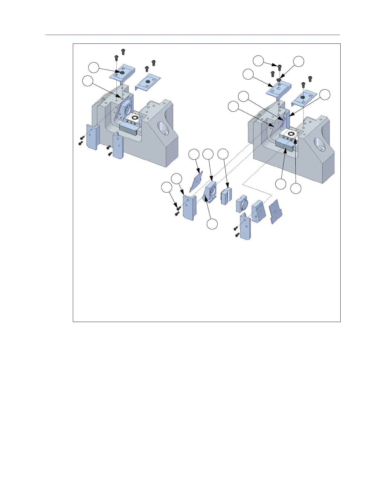
Figure 17. Components of the grip assemblies for G7-style crossheads.
1. Guide plate (front and rear)
2. Socket head cap screw (see Table 12 on
page 51 for size, quantity and torque)
3. Wear plate
4. Jaw carrier
5. Guide pin
(one on each side of jaw carrier)
6. Grip jaw
7. G rip poc ke t
8. Guide slot for guide pin
9. Push plate and piston
10. Piston dust cover
11. Grip dust cover
12. Button head cap screw (see Table 12 on
page 51 for size and quantity)
13. Grease fitting plug
14. Grease fitting
2
13
14
1
3
4
6
5
10
9
7
8
11
12
13
1

Table of Contents

Other manuals for Instron DX Series

Questions and Answers:

Question and Answer IconNeed help?

Do you have a question about the Instron DX Series and is the answer not in the manual?

Instron DX Series Specifications

General IconGeneral
BrandInstron
ModelDX Series
CategoryTest Equipment
LanguageEnglish

Related product manuals