CombiLock 200 simplex / pro / RFID
Handbuch V.1.05 72 Manual V. 1.05
2. Shorten spindle halves / shorten spindle. Assemble spindle variant A using 2
halve pipes and 1 cuff. Thread the cable with its plug through the spindle.
Lead the spindle through the safe door bore. Attach the 2
nd
cuff.
3. Thread the keypad connector cable with its plug through the spindle
variant B and the centre axis of the electronic lock.
4. Insert the connecting spindle into the keypad and adjust its position in
relation to the electronic lock.
5. Slip-on the locked electronic lock onto the spindle.
6. Use three steel machine screws (M6 x 30 mm, DIN 6912, flat form or the
corresponding inch threads) to affix the electronic lock so that permanent
and secure support is provided.
In order to avoid malfunctions, tighten down the mounting screws with a torque of
max. 10 Nm. If required, additionally use screw retention liquid of medium
mechanical strength
Installation options: The electronic lock must always be located at right
angles to the keypad (four installation positions, each
offset 90° from the other).
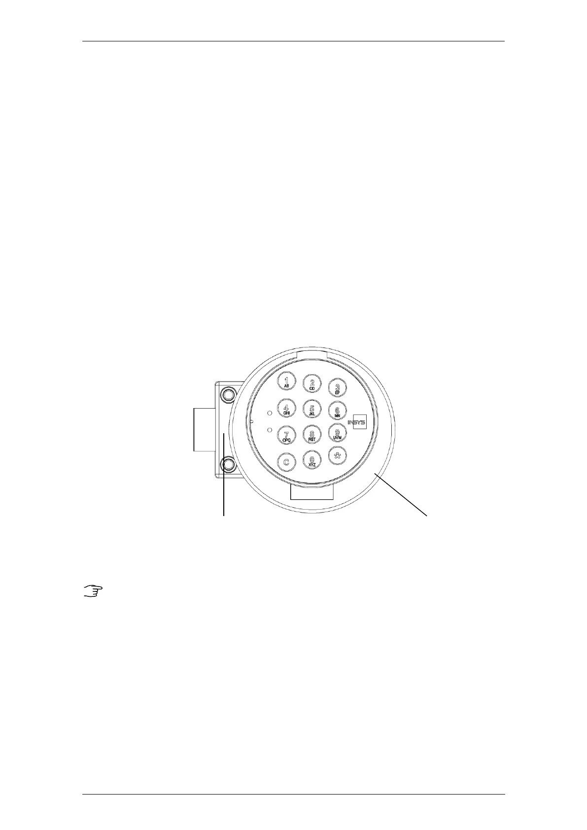
INSYS Lock 200 simplex / pro / RFID CombiControl
Sample installation of electronic lock system CombiLock 200 simplex / pro / RFID
The bolt is not to be subjected to tension or pressure after installation.
Do not use lubricants or any other substances on or in the electronic lock.
The system is maintenance-free in normal office environment. We
recommend to have a security check and a functional test performed by
personnel trained by INSYS MICROELECTRONICS after about 10,000
closing cycles.