CombiLock 200 simplex / pro / RFID
Handbuch V. 1.05 67 Manual V.1.05
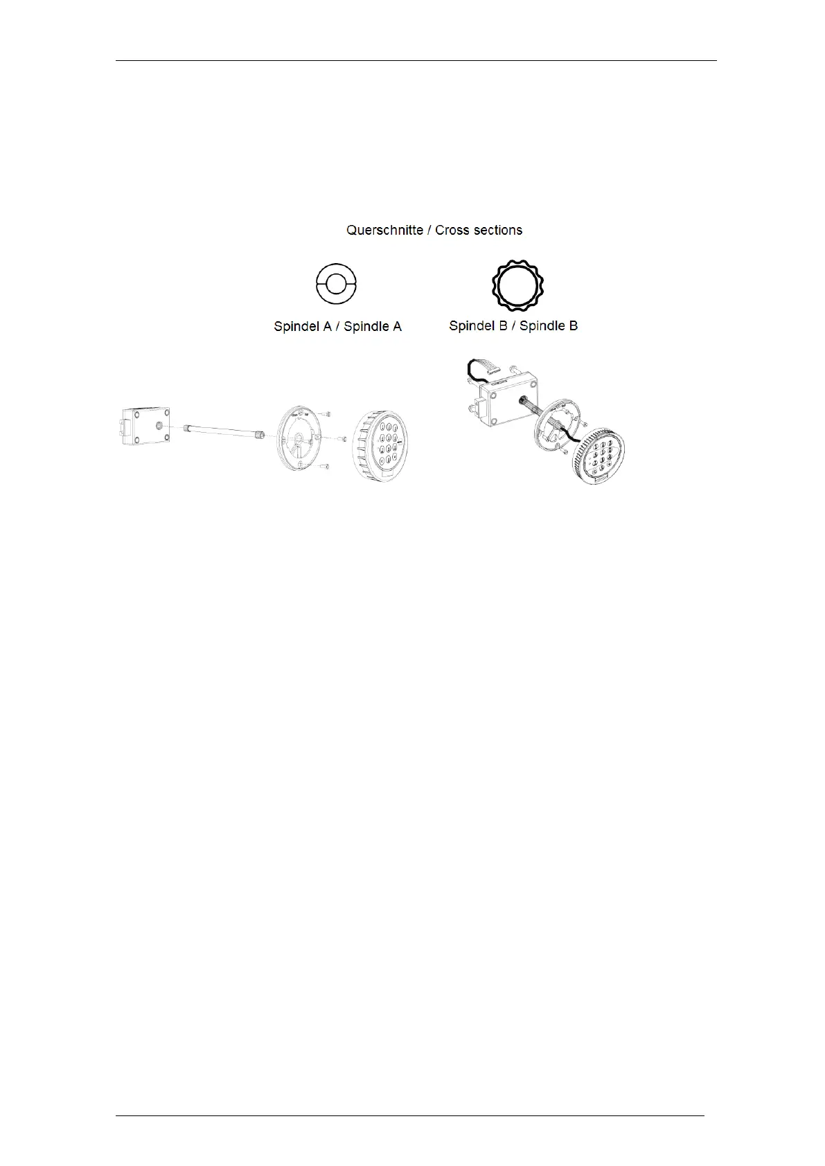
7.1 Assembly - Overview
There are 2 variants of the spindle, A and B.
Spindle A (below on the left hand side) consists of two half pipe pieces and cuffs.
Spindle variant B (below on the right) is a pipe.
System with spindle variant A System with spindle variant B
The attachment ring is to be mounted at the door with 4 cylinder screws M4x10.
Fasten the lock using 3 x cylinder screws.
7.2 Assembly Sequence
7.2.1 Checking on Bores / Drilling the Bores
Also see drawings and text of sections 7.2.4 and 7.2.6.
Check whether there are bores required for the spindle, the attachment ring and
the lock already drilled into the safe door.
If required and if you have a system with a spindle variant A:
Drill a hole of min. 8.2 mm, max. 12 mm in diameter into the door of the safe.
Observe drawings and text of section 7.2.4.
If you have a system with a spindle variant B:
Drill a hole of min. 10.5 – max 13 mm in diameter, into the safe door.
Observe drawings and text of section 7.2.4.
Drill further bores, if required, at this stage, or, as recommended, when following
the steps of sections 7.2.4 and 7.2.6.
With a system containing the connecting spindle variant A, skip point 7.2.3 below.
With a system containing the connecting spindle variant B, skip point 7.2.2 below.