CombiLock 200 simplex / pro / RFID
Handbuch V. 1.05 71 Manual V.1.05
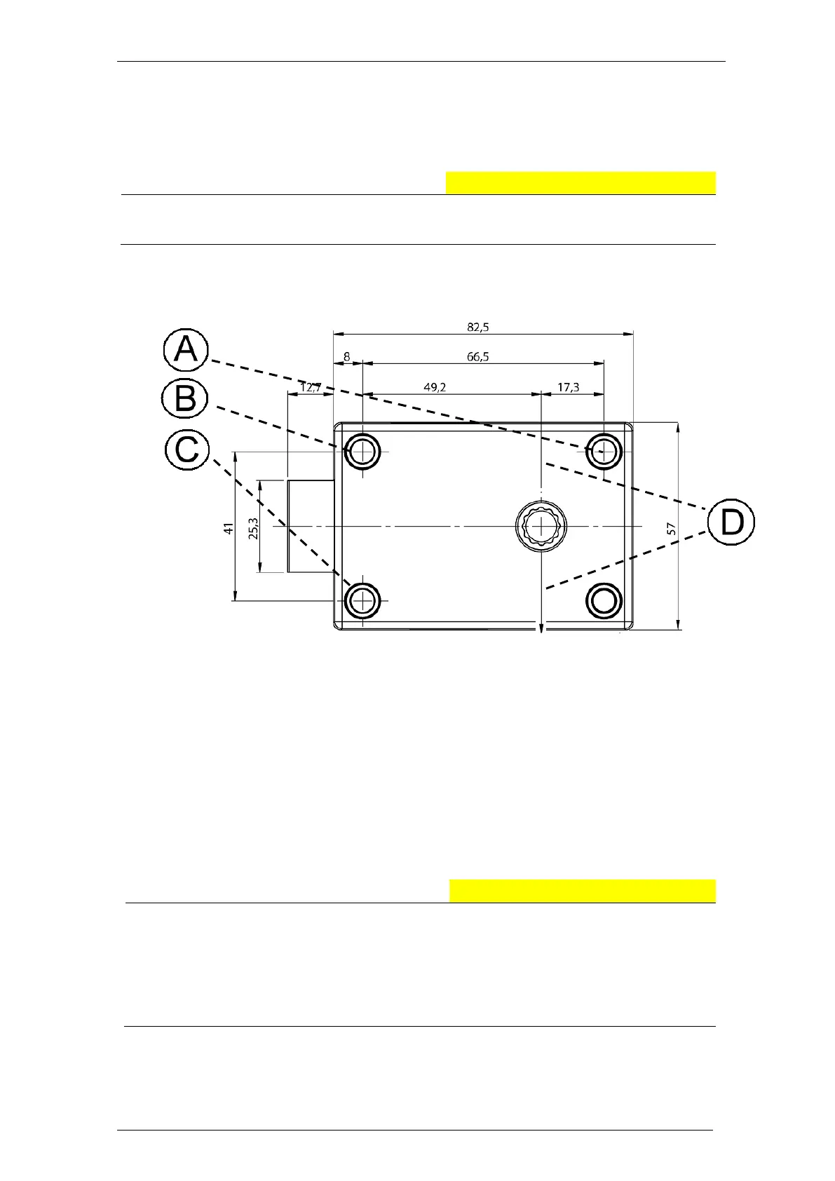
7.2.6 Drilling Holes for the Lock
Uneven surfaces may cause functional loss.
Make sure that the lock is mounted onto an even surface.
Drill 3 threaded holes M6 according to the drawing below in order to prepare the
attachment of the electronic lock.
A) Bore for the attachment of the lock
B) Bore for the attachment of the lock
C) Bore for the attachment of the lock
D) Centre shaft of electronic lock
7.3 Mounting the Lock
Also see the assembly overview above.
Applying too much force can cause damage.
Consequences which might arise from not being aware of
the danger.
Do not use more torque than 5 Nm when fastening the
attachment ring and do not use more torque than 10 Nm when
fastening the lock.
1. Check whether there are suitable bores in the safe door. If required, drill
bores, at this stage above all for the spindle variant A (Ø min. 8.2 mm, max.
12 mm).
Drill further bores, if required, before carrying out steps 3 - 6 ( see below).