INTEC Controls | 12700 Stowe Drive, Suite 100, Poway, CA 92064 | Ph: (858) 578.7887 & (888) GO.INTEC | inteccontrols.com
Specifications subject to change without notice. | GAGC06_E_0516 | USA 200303 | Page 17 of 41
DGC6 – UserManual
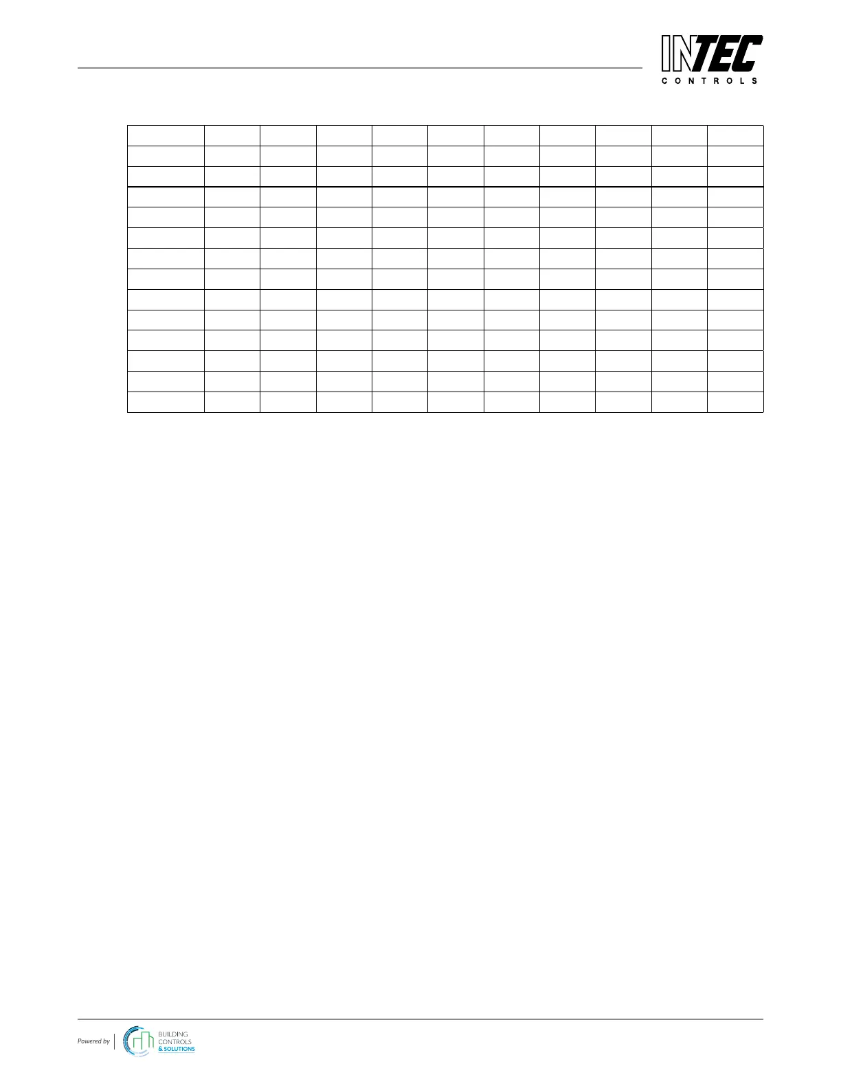
(The headlines and column numbers are only for easy explanation and aren’t written in the le!)
Column 1 2 3 4 5 6 7 ... 98 99 etc.
Time 1 2 3 4 5 6 ... 97 98 x
or time DP1 DP2 DP3 DP4 DP5 DP6 ... AP1 AP2
09_50_02 0 20 20 28 0 - ... 0 0
09_50_03 0 20 20 28 0 - ... 25 29
09_50_04 0 20 20 28 0 - ... 25 29
09_50_05 0 20 20 28 0 - ... 25 29
09_50_06 0 20 20 28 0 - ... 25 29
09_50_07 0 20 20 28 0 - ... 25 29
09_50_08 0 20 20 28 0 - ... 25 29
09_50_09 0 20 20 28 0 - ... 25 29
09_50_10 0 20 20 28 0 - ... 25 29
09_50_11 0 20 20 28 0 - ... 25 29
09_50_12 0 20 20 28 0 - ... 0 29
The rst column gives the time; from the second column on, the current values of all registered measuring points at
this time are written. Inactive measuring points within active measuring points are marked by a dash -.
Values less than 0 stands for an error status of the measuring point.
e.g. 0x8100 = Underrange of head of measuring point
e.g. 0x8200 = Overrange of head of measuring point
e.g. 0x9000 = Communication error of sensor board of measuring point
e.g. 0xB000 = Communication error of head of measuring point
Each error is marked by the prex 0x.
In this way the le keeps a xed structure and can be evaluated with Excel and graphed according to the chronological
sequence.
 Loading...