INTEC Controls | 12700 Stowe Drive, Suite 100, Poway, CA 92064 | Ph: (858) 578.7887 & (888) GO.INTEC | inteccontrols.com
Specifications subject to change without notice. | GAGC06_E_0516 | USA 200303 | Page 28 of 41
DGC6 – UserManual
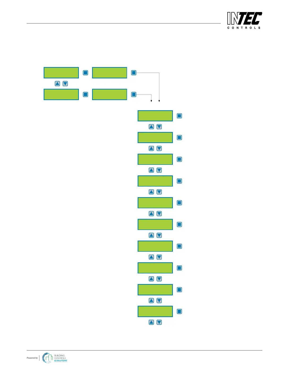
4.8.3 Menu SP Parameters
For reading and changing measuring point parameters for each bus and analog sensor including registration of SP
and assignment of the alarm relays.
DP 1
active
Digital SP
Parameters
Submenu 1
Selection of digital measuring point (1-96)
Submenu 2
Analog SP
Parameters
AP 1
active
Selection of analog measuring point (1-32)
Submenu 3
SP Mode
not active
Temporary Mode
unlocked / locked
Nom./Gas/Unit
1110 CO ppm
Measuring Range
250 ppm
Stage/Setpoint 1
C 25 ppm
Stage/Setpoint 2
C 50 ppm
Stage/Setpoint 3
C 75 ppm
Hyeresis
10 ppm
Stage/Setpoint 4
C 100 ppm
CV time ON delay
0 s
Activate or deactivate SP
See 4.8.3.1
Activation of a temporary blocking
See 4.8.3.2
Denition of gas type with unit
See 4.8.3.3
Denition measuring range
See 4.8.3.4
Denition alarm threshold 1
See 4.8.3.5
Denition alarm threshold 2
See 4.8.3.5
Denition alarm threshold 3
See 4.8.3.5
Hysteresis
See 4.8.3.5
Denition alarm threshold 4
See 4.8.3.5
Delay time for alarm ON
See 4.8.3.6
Changes only possible in code level priority 1
 Loading...