INTEC Controls | 12700 Stowe Drive, Suite 100, Poway, CA 92064 | Ph: (858) 578.7887 & (888) GO.INTEC | inteccontrols.com
Specifications subject to change without notice. | GAGC06_E_0516 | USA 200303 | Page 33 of 41
DGC6 – UserManual
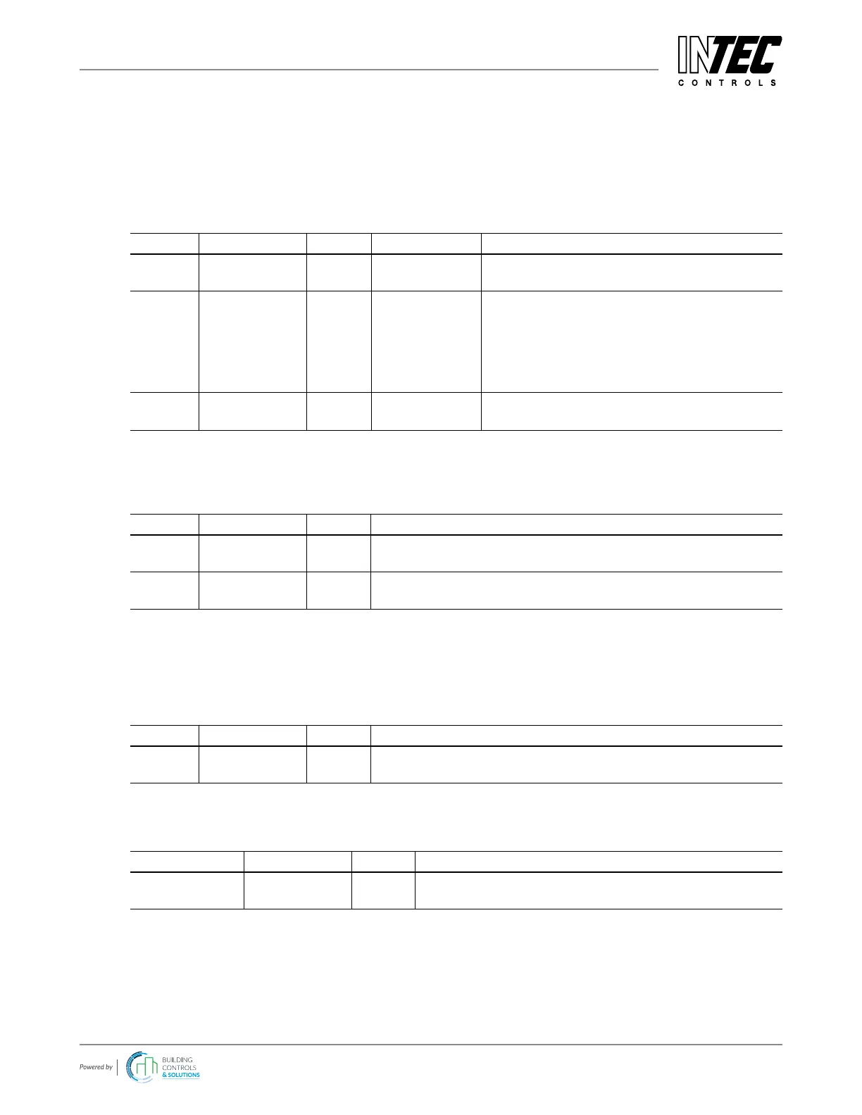
4.8.3.5 Stage Setpoint / Hysteresis
For each measuring point four alarm thresholds can be dened. If the gas concentration is higher than the set alarm
threshold, the associated alarm is activated. If the gas concentration falls below the alarm threshold by the hysteresis
value the alarm is automatically reset. In the mode “Alarm at falling” the corresponding alarm is set in case of falling
below the set alarm threshold and reset again when exceeding the threshold plus hysteresis. The display depends on
the set measuring range: see 4.8.3.4. Unused alarm thresholds have to be dened at measuring range end point, in
order to avoid undesired alarms. Higher-level alarms automatically activate the lower-level alarms.
Symbol Description Default Function Symbol
A Evaluation A A
C
A = Alarm evaluation with average value of SP
C = Alarm evaluation with current value of SP
80 ppm Alarm threshold
25
50
75
100
10
Stage Setpoint 1
Stage Setpoint 2
Stage Setpoint 3
Stage Setpoint 4
Hysteresis
Gas concentration > Threshold 1 = Alarm 1
Gas concentration > Threshold 2 = Alarm 2
Gas concentration > Threshold 3 = Alarm 3
Gas concentration > Threshold 4 = Alarm 4
Gas concentration < (Threshold X –Hysteresis)
= Alarm X OFF
= Alarm release at increasing concentrations
= Alarm release at falling concentrations
4.8.3.6 Delay for Alarm ON and/or OFF for Current Value Evaluation
Denition of delay time for alarm ON and/or alarm OFF. The delay applies to all alarms of an SP, not with average
value overlay, see 4.8.3.7.
Symbol Description Default Function
0 s
CV Alarm ON
delay
0
Gas concentration > Stage/Setpoint: Alarm is only activated at the
end of the xed time (sec.). 0 sec. = No delay
0 s
CV Alarm OFF
delay
0
Gas concentration < Stage/Setpoint: Alarm is only deactivated at
the end of the xed time (sec.). 0 sec. = No delay
4.8.3.7 Average Overlay (VDI 2053 Functionality)
The alarm evaluation of the operation mode “Average” is overridden by the current value, if this exceeds the alarm
threshold dened in the menu “System Setup AV Overlay” (see 4.8.4.4). The overlay is delayed by the time factor
entered in the local menu. The function of the average overlay is only evaluated for the gas type CO and is activated
here.
Symbol Description Default Function
Yes AV Overlay Yes
Yes = Average overlay active (for CO)
No = Average overlay not active
4.8.3.8 Latching Mode Assigned to Alarm
In this menu you can dene, which alarms should work in latching mode.
Symbol Description Default Function
Alarm - 1 2 3 4
SBH - 0 0 0 0
Latching SP 0 0 0 0
0 = No latching
1 = Latching
 Loading...