INTEC Controls | 12700 Stowe Drive, Suite 100, Poway, CA 92064 | Ph: (858) 578.7887 & (888) GO.INTEC | inteccontrols.com
Specifications subject to change without notice. | GAGC06_E_0516 | USA 200303 | Page 37 of 41
DGC6 – UserManual
4.8.4.8 Analog Output
The Gas Controller Module as well as the EP modules 1 to 7 have two analog outputs (AO) with 4 to 20 mA signal
each. The signal of one or more measuring points can be assigned to each of the analog outputs; in this case, the
signal control becomes active and the output is current monitored. The signal monitoring is self-healing and therefore
must not be acknowledged. The assignment is done in the menu “SP Parameter” for each SP. The measuring point
sends the current value signal to the analog output.
Out of the signals of all assigned measuring points the Gas Controller determines the minimum, the maximum or the
average value and transmits it to the analog output. The denition, which value is transmitted, is done in the menu
“Analog Output X”.
To allow exible air volume regulation of speed-controlled motors, the slope of the output signal can be adapted to the
on-site conditions and varied between 10 - 100%.
As an alternative to the activation via the controller (dened by the number 1), the analog inputs can be assigned to
the analog outputs of the same EP module (menu in the EP module). For this purpose, the number 10 - 100% has to
be entered on the EP module.
Symbol Description Default Function
Analog
Output 1
Selection of
channel
0 Selection of the analog output 1-16
0
1
10-100 %
Selection of
output signal
100%
0 = Analog output is not used
(therefore always de-activated response monitoring)
1 = Local use (not used in the central control)
Selection of signal slope- permitted range 10-100 %
100% gas signal control = 20 mA
10% gas signal control = 20 mA (high sensitivity)
C
Selection of
source
C
C = Source is current value
A = Source is average value
CF = Source is current value and additional fault message at AO
AF = Source is average value and additional fault message at AO
Max.
Selection of
output mode
Max.
Min. = Displays the minimum value of all assigned SP
Max. = Displays the maximum value of all assigned SP
Average = Displays the average value of all assigned SP
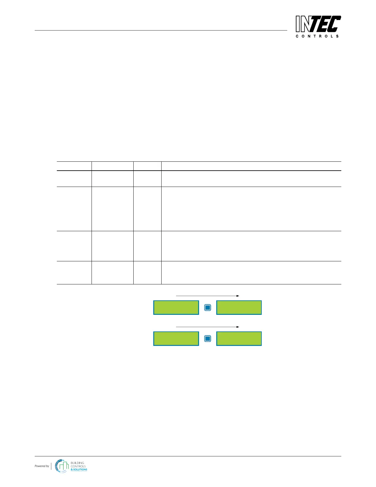
Analog Output 1
100% C Max.
AO Function
Example 1
Analog Output 1
40% C Max.
AO Function
Example 2
4.8.4.9 Relay Multiplication
With the relay multiplication table, it is possible in the DGC6 system to assign additional relays to an alarm. This
corresponds in the end to one multiplication of the source alarm situation per entry.
The additional relay follows the alarm status of the source, but uses its own relay parameters to allow dierent needs
of the doubled relay. So the source relay can be congured, for example, as safety function in de-energized mode, but
the doubled relay can be declared with ashing function or as horn function.
There is a maximum of 20 entries for IN relays and OUT relays. Thus it is possible, for example, to expand one relay to
19 others or to double max. 20 relays.
 Loading...