13
Connecting antennas
To use the tuner of the DTM-5.3, it is necessary to prepare the supplied FM and AM antennas.
• Adjustment and placement of the FM and AM antennas for better reception is best performed while listening to a station broadcast.
• If better reception cannot be obtained, then placement of an outside antenna is recommended.
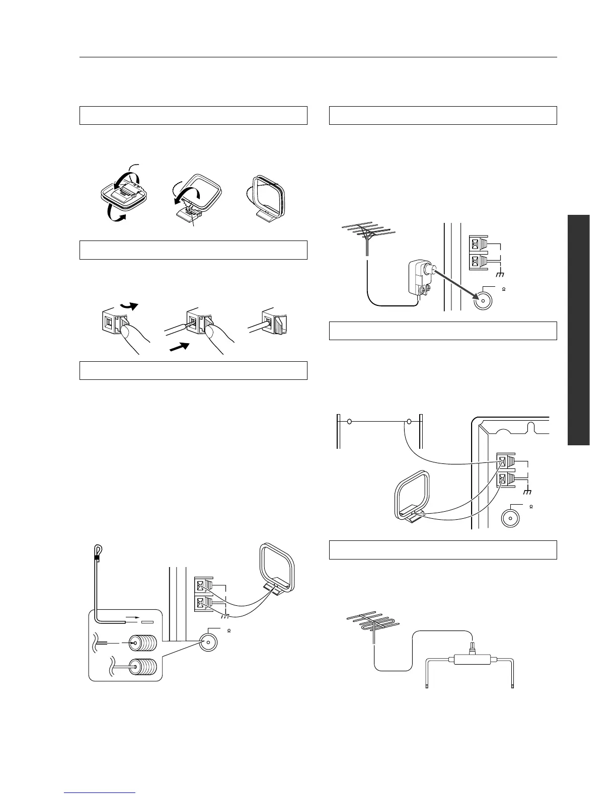
Assembling the AM loop antenna
Assemble the loop antenna as shown in the illustration.
• Refer to “Connecting the AM loop antenna” below for details
on connecting the loop antenna.
Connecting the AM antenna cable
1. Push the lever.
2. Insert the wire into the hole.
3. Release the lever.
Connecting the included antennas
Connecting the FM indoor antenna:
The FM indoor antenna is for indoor use only. During use, extend
the antenna and move it in various directions until the clearest sig-
nal is received. Fix it with push pins or similar implements in the
position that will cause the least amount of distortion.
If the reception is not very clear with the attached FM indoor
antenna, the use of an outdoor antenna is recommended.
Connecting the AM loop antenna:
The AM loop antenna is for indoor use only. Set it in the direction
and position in which you receive the clearest sound. Locate it as
far away as possible from the DTM-5.3, televisions, speaker
cables, and power cords.
When reception is not satisfactory with the attached AM loop
antenna alone, connection of an outdoor antenna is recommended.
Hint:
Either of the split ends of the AM antenna can be connected to
either terminal. Unlike speaker cabling, there is no polarity for AM
broadcast signals.
Connecting an FM outdoor antenna
Please make sure that you follow these guidelines:
• Keep the antenna away from noise sources (neon signs, busy
roads, etc.).
• It is dangerous to locate the antenna close to power lines. Keep
it well away from power lines, transformers, etc.
• To avoid the risk of lightning and electrical shock, grounding is
necessary. Follow item 14 of the “Important Safeguards” on
page 2 when you install the outdoor antenna.
Connecting an AM outdoor antenna
An outdoor antenna will be more effective if it is stretched horizon-
tally above a window or outside.
• Do not remove the AM loop antenna.
• To avoid the risk of lightning and electrical shock, grounding is
necessary. Follow item 14 of the “Important Safeguards” on
page 2 when you install the outdoor antenna.
Directional linkage
Do not use the same antenna for both FM and TV (or VCR) recep-
tion since the FM and TV (or VCR) signals can interfere with each
other. If you must use a common FM/TV (or VCR) antenna, use a
directional linkage type splitter.
Insert into the hole.
12
3
ANTENNA
FM
75
AM
(indoor)
AM loop
antenna
FM antenna
Strip away the insulation from the
end of the cable, then fully insert
the stripped end of the cable.
ANTENNA
FM
75
AM
ANTENNA
FM
75
AM
Outdoor
antenna
(indoor)
AM loop
antenna
Directional linkage
type splitter
To DTM-5.3 To TV (or VCR)