17
Installing the remote controller batteries
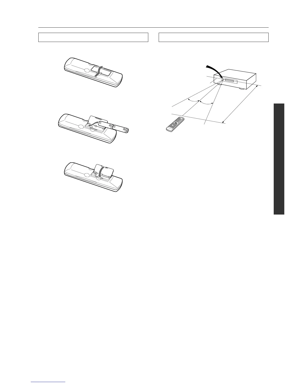
Installing the batteries
1 Open the battery compartment cover by pushing the tab
and opening the cover.
2 Insert two AA (R6 or UM-3) batteries into the battery
compartment. Carefully follow the polarity diagram (pos-
itive (+) and negative (–) symbols) inside the battery
compartment.
3 After batteries are installed and seated correctly, replace
the compartment cover.
Notes:
• Do not mix new batteries with old batteries or different kinds of
batteries.
• To avoid corrosion, remove the batteries if the remote controller
is not to be used for a long time.
• Remove dead batteries immediately to avoid damage from cor-
rosion. If the remote controller does not operate smoothly,
replace both the batteries at the same time.
Remote controller operation
Point the remote controller toward the remote control sensor. The
Standby indicator lights up when the unit receives a signal from the
remote controller.
Notes:
• Place the unit away from strong light such as direct sunlight or
inverted fluorescent light, which can prevent proper operation of
the remote controller.
• Using another remote controller of the same type in the same
room or using the unit near equipment that uses infrared rays
may cause operational interference.
• Do not put objects on the remote controller. Its buttons may be
pressed by mistake and drain the batteries.
• Make sure the audio rack doors do not have colored glass.
Placing the unit behind such doors may prevent proper remote
controller operation.
• If there is any obstacle between the remote controller and the
remote control sensor, the remote controller will not operate.
DTM-5.3
Standby indicator
Remote control sensor
30˚
30˚
approx. 5 m
(16 feet)