28
Using the remote controller
Setting the ID number
Programming the remote controller ID (This procedure is not
required if you are using only one DTM-5.3.)
If you are using multiple DTM-5.3 units, all units will respond to
an operation on one of the remote controllers. To avoid this, you
can establish up to nine ID numbers for the remote controllers.
The same ID number should be set on both the remote controller
and the corresponding DTM-5.3. You can use the remote controller
as long as its ID matches that specified on the main unit.
To cancel the ID number, set the number to “0.” If the ID on the
main unit is set to “0,” all remote controllers (with ID 0-9) can con-
trol the unit.
Programming the ID number
1 On the remote controller, while pressing and holding
down the RCVR/Tape button, press the Enter button,
then release both buttons.
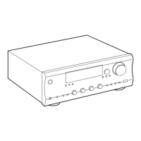
2 Press one of the number buttons (1–9, 0).
The number you pressed is set as the ID.
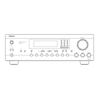
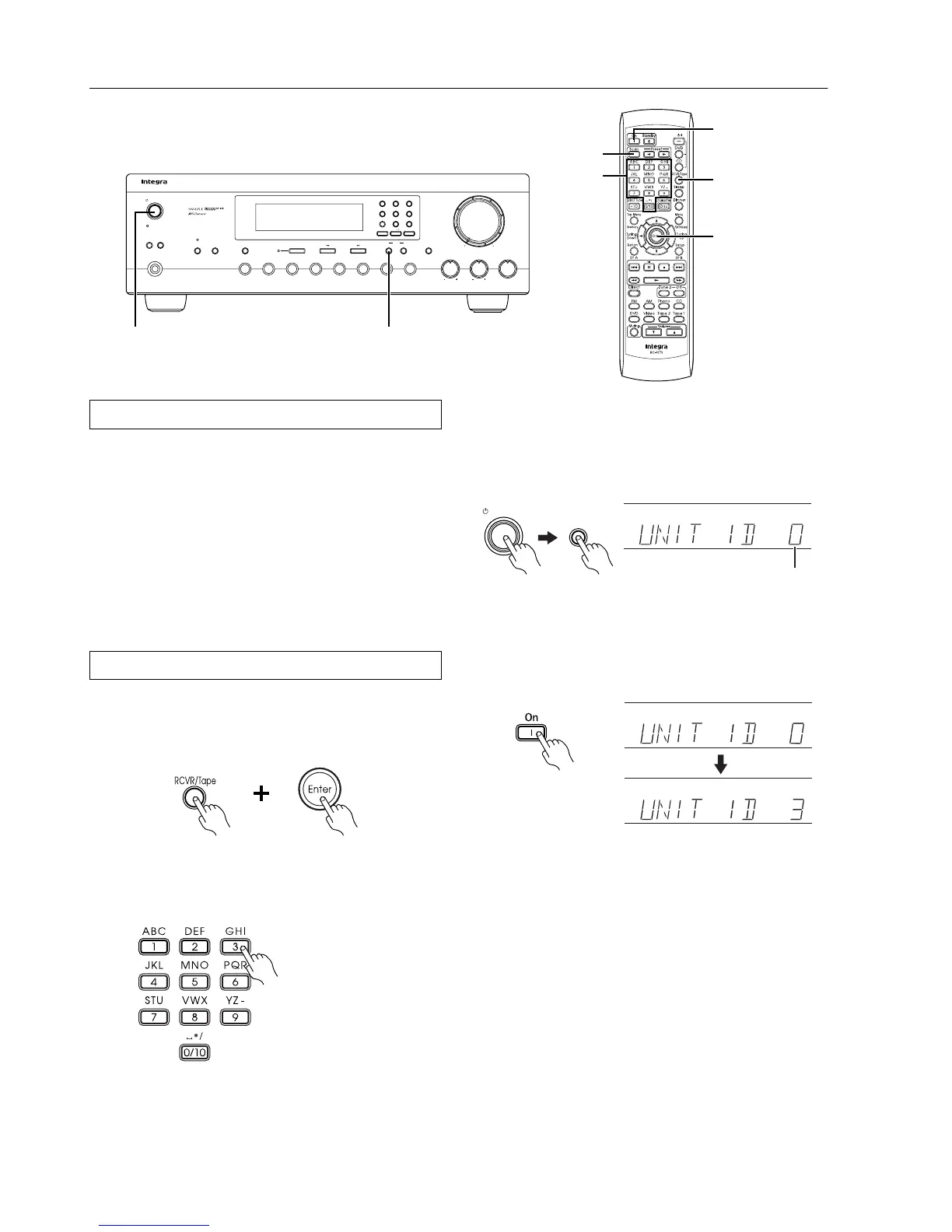
3 Turn on the power to the DTM-5.3, and press and hold
down the Memory button.
The current ID number of the main unit appears on the display
for five seconds.
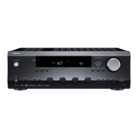
4 While the current ID of the unit appears on the display,
press the On button on the remote controller.
The remote controller will send its ID information to the unit,
and the ID of the unit will be changed to match the remote con-
troller’s ID.
For example, if you press “3” in Step 2:
“UNIT ID 0” ➔ “UNIT ID 3”
The unit’s ID will change to “3.”
Hint:
You can use the number buttons on the main unit instead of press-
ing the On button on the remote controller. In this case, press the
same number as the remote controller’s ID (selected in Step 2).
Checking the remote controller’s ID:
Press the Scan button on the remote controller while the display
indication shown in Step 4 appears. The remote controller’s ID
appears on the display.
E.g., REMOTE ID 3
Note:
The unit will not respond to remote controller operations if the ID
numbers do not match.
Standby/On
Speakers
A
B
Phones
Bass
Treble Balance
L
R
Master Volume
Video
Tape 2
Monitor
Tape 1
FM
AM Phono CDDVD
Zone 2 Off
Memory
Clear
Character
Direct Tuning
FM Mode
Display
Standby
DTM
-
5.3
1 ABC 2 DEF 3 GHI
4 JKL
5 MNO 6 PQR
7 STU 8 VWX 9 YZ
-
Direct Tuning 0
/
10
/
Scan
Standby/On Memory
On
Number
buttons
Scan
RCVR/Tape
Enter
Remote controller
Remote controller
E.g.,
Press “3.”
Memory
Standby/On
DTM-5.3 (this unit)
Current ID
Remote controller
Remote controller