100Base-TX Test Procedure for the 82544 Chip
1000BASE-T/100BASE-TX/10BASE-T Physical Layer Compliance Tests Manual
138 Intel Confidential
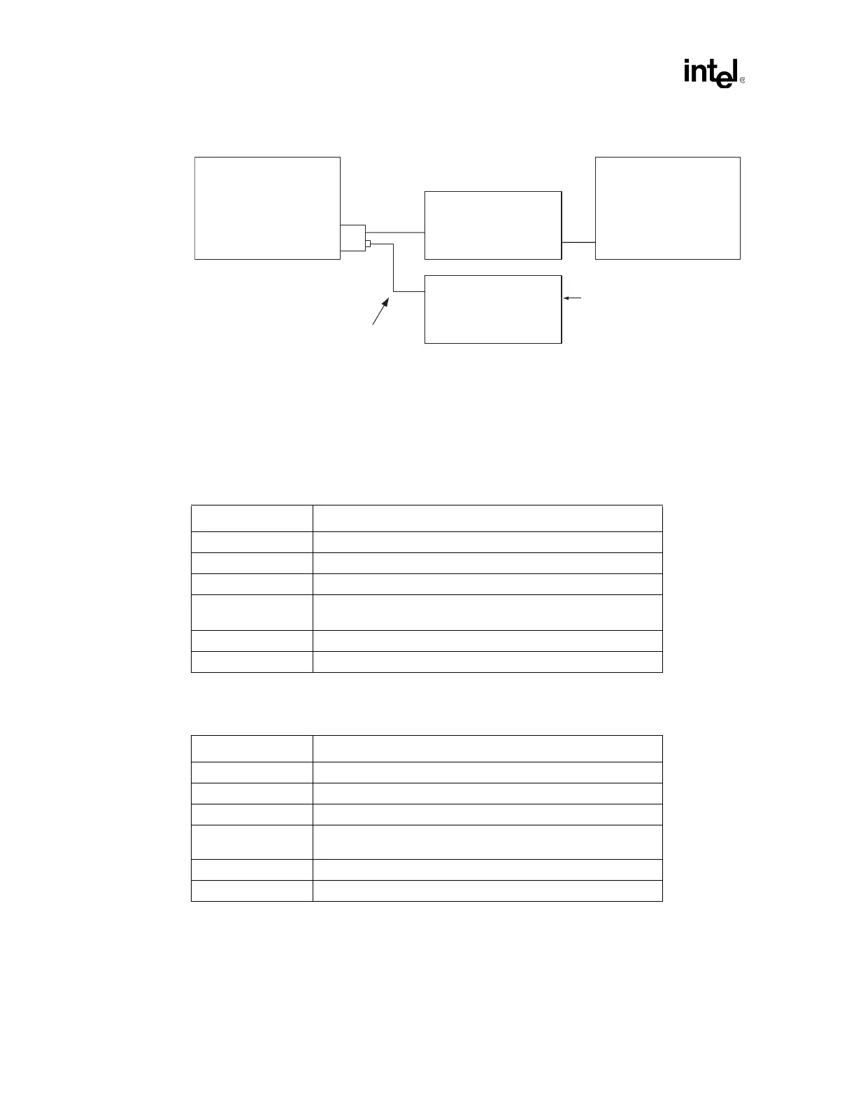
Figure I-2. Test Setup Number
UUT
RJ-45
Differential
Probe
w/ 1 GHz BW
Digitizing
Oscilloscope
TX
RX
Short CAT5 cable with female
pins on one end and an RJ-45
on the other.
RJ-45
Link partner LAN adapter in 100 Mbps
mode transmitting scrambled idles
Table I-1. For Positive Peak Differential Output Amplitude (see Figure I-3)
Scope Parameter Setting
Horizontal Scale ~25 ns/division
Vertical Range -100 mV to +1100 mV (1200 mV over the full vertical scale)
Vertical Position -3.5 divisions to -4.0 divisions
Trigger Type
Positive, Pulse Width Triggering:
~108 ns lower bound, ~116 ns upper bound
Trigger Level +500 mV
Trigger Signal Differential signal at the pins of the test load.
Table I-2. For Negative Peak Differential Output Amplitude (see Figure I-4)
Scope Parameter Setting
Horizontal Scale ~25 ns/division
Vertical Range -1100 mV to +100 mV (1200 mV over the full vertical scale)
Vertical Position +3.5 divisions to +4.0 divisions
Trigger Type
Negative, Pulse Width Triggering:
~108 ns lower bound, ~116 ns upper bound
Trigger Level -500 mV
Trigger Signal Differential signal at the pins of the test load.