1000BASE-T Peak Differential Output Voltage and Level Accuracy
1000BASE-T/100BASE-TX/10BASE-T Physical Layer Compliance Tests Manual
10 Intel Confidential
2.3 Test Equipment
•
Digitizing oscilloscope with at least 1 GHz bandwidth
•
Differential probe with 1 GHz or greater bandwidth
•
UUTu with gigconf.exe test software
2.4 Test Fixtures
•
100 Ω UTP test load (Appendix A.1).
2.5 Test Procedure
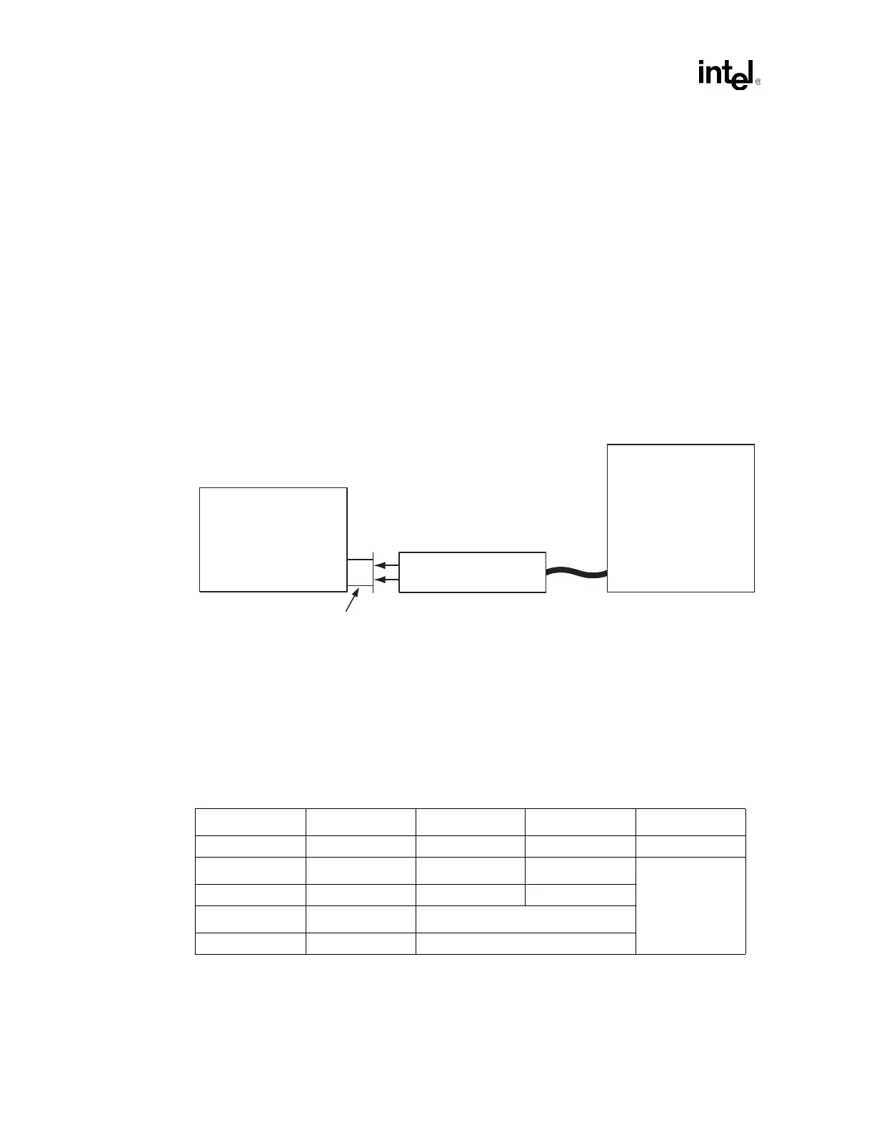
1. Connect the test equipment as shown in the figure below.
2. Set the probe to divide by 10 and to full bandwidth.
3. Select the Amplitude and Level Accuracy: 40.6.1.2.1 Test from the 1000BASE-T PHY
Configuration Tests menu in gigconf.exe.
4. Measure the output voltage with a differential probe connected across the 100-ohm test load
for each channel.
5. Adjust oscilloscope to the settings for Point A as shown in the following table and figure:
Differential Probe
w/ 1 GHz BW
Unit Under Test
(UUT)
Digitizing
Oscilloscope
Test Fixture 40-25
100 Ohm Resistive Load
RX
RJ-45
TX
Table 2-1. Point A Peak Voltage
Trigger Settings Trigger Type Polarity Limits Level
Pulse width Positive 7 ns to 9 ns +500 mV
Scaling Vertical Scale Vertical Position Horizontal Scale
150 mV / division -3.0 division 5 ns / division
Cursors Display Mode Acquisition Mode
Horizontal bars Vectors Average on