1000BASE-T/100BASE-TX/10BASE-T Physical Layer Compliance Tests Manual
Intel Confidential 137
100Base-TX Test Procedure for the 82544 Chip
I.3.3 Specification
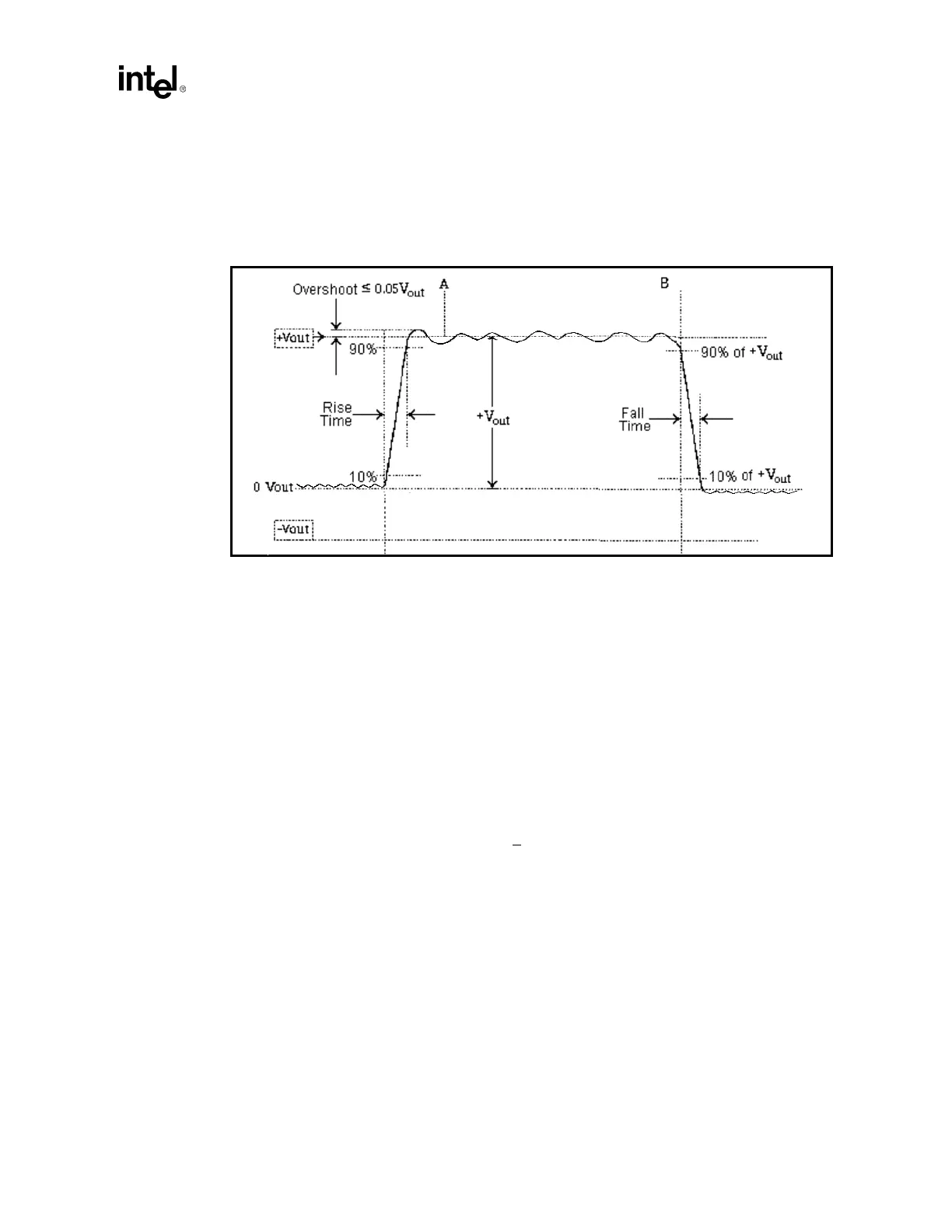
At the RJ-45 connector, the differential output voltage, +Vout, shall be within the range between
+950 mV and +1050 mV, and Vout, shall be within the range between -950 mV and -1050 mV. See
Figure I-1.
Figure I-1. Waveform at Active Output Interface
I.3.4 Test Equipment
•
Digitizing Oscilloscope with at least 1 GHz bandwidth
•
Differential Probe with 1 GHz or greater bandwidth (like P6247)
•
Host computer with gigconf.exe software (for 82554 silicon).
I.3.5 Test Fixtures
100 Ohm UTP Test Load. Fixture: F9.1.2.A.
The test load shall consist of a single 100 ohm +
0.1% resistor connected across the transmit pins of
a mating RJ-45 connector. The series inductance of the load shall not be greater than 20 nH, and the
parallel capacitance shall not be greater than 2 pF.
I.3.6 Test Procedure
1. Connect the Test equipment and Unit Under Test (UUT) as shown in Figure I-2 on page I-138
(which shows the setup for test specifications 9.1.2.2, 9.16, and 9.1.8).
2. Use software or firmware control to force the unit under test to transmit frames in 100BASE-
TX mode. The data pattern is NOT important. Leave Scrambling ENABLED (the phy’s default
or normal mode of operation).
3. Configure the oscilloscope according to Table I-1 and Table I-2.