1000BASE-T/100BASE-TX/10BASE-T Physical Layer Compliance Tests Manual
Intel Confidential 125
Troubleshooting Guide
G.4 Overshoot (ANSI specification 9.1.3)
Excessive overshoot can cause problems because other receivers may not be designed to
compensate for large amounts of overshoot.
It is absolutely imperative that low capacitance/high bandwidth probes be used for these
measurements. Probes with greater than 1 pf capacitance and/or less than 1 GHz bandwidth may
show false failures.
The value of the coupling capacitor between TDP and TDN should be increased in order to
decrease transmit overshoot. However, increasing the value of this capacitor will reduce the
transmit return loss. Additionally, it will increase the rise and fall times. Thus, an optimal value
should be found through experimentation. A valid range for this capacitor on the 82558 is from 0
pF to 20 pF, with an average value of between 7 pF and 15 pF depending on the design. The
required value of this capacitor is affected by both trace and magnetics capacitance.
G.5 Amplitude Symmetry (ANSI specification 9.1.4)
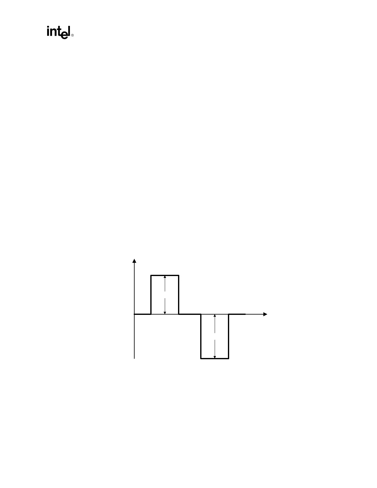
Incorrect amplitude symmetry can have a couple of undesired effects. First, it can decrease the
distance apart two network stations can be before performance starts to seriously degrade. Assume
that the receiver can pick up a 1 V peak signal over 100 meters of spec length cable. If the signal is
asymmetric as shown in the figure below, the signal will only be able to be received to 95 meters of
spec length cable. Even though the negative peak is 1050 mV, the limiting factor is the positive
peak which is 950 mV.
Figure G-1. Asymmetric Amplitudes
Additionally, asymmetric amplitudes could cause problems with the receiver’s peak detectors,
because they may be expecting both the positive and negative peaks to be at the same level. They
could try to adjust the signal to make the peaks equal by adding in a DC offset, and in doing so
would distort the waveform even more (because the zero point would become ambiguous).
Voltage
Time
950 mV
1050 mV