100BASE-TX Differential Output Voltage (UTP)
1000BASE-T/100BASE-TX/10BASE-T Physical Layer Compliance Tests Manual
32 Intel Confidential
8.4 Test Fixtures
100 Ω UTP test load (Appendix A.1)
8.5 Test Procedure
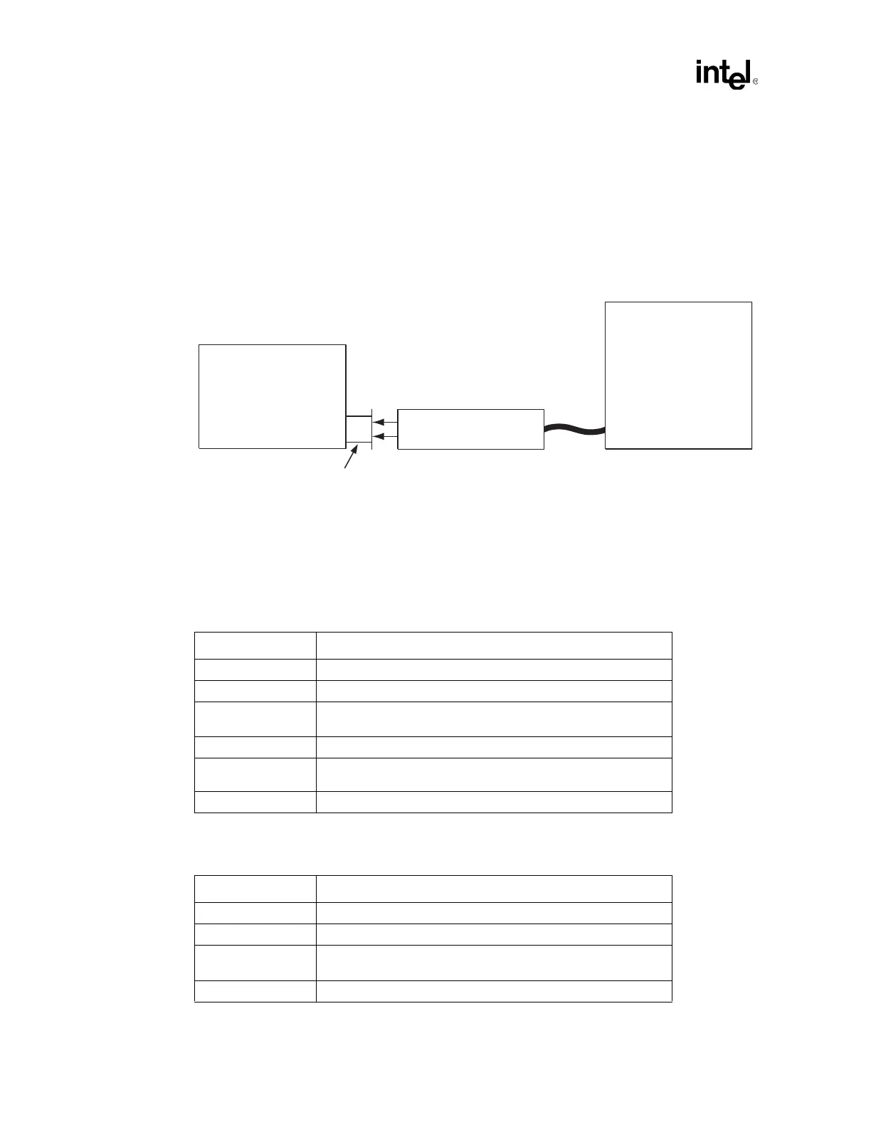
1. Connect the test equipment and UUT as shown below.
Figure 8-2. Test Setup for 100BASE-TX Differential Output Voltage
2. From the 100BASE-TX PHY Configuration Tests menu in gigconf.exe, select the Amplitude:
9.1.2.2 test.
3. Configure the oscilloscope according to Table 8-1.
Differential Probe
w/ 1 GHz BW
Unit Under Test
(UUT)
Digitizing
Oscilloscope
Test Fixture 40-25
100 Ohm Resistive Load
RX
RJ-45
TX
Table 8-1. Setting for Positive Differential Output Voltage (UTP)
Scope Parameter Setting
Horizontal Scale ~25 ns/division
Vertical Range -150 mV to +1050 mV (1200 mV over the full vertical scale)
Trigger Type
Positive pulse width triggering:
116 ns lower bound, 128 ns upper bound
Trigger Level 500 mV
Record Length
Large enough to enable viewing of one complete MLT-3 (3-level)
waveform by scrolling horizontally
Display Type Average
Table 8-2. Setting for Negative Differential Output Voltage (UTP)
Scope Parameter Setting
Horizontal Scale ~25 ns/division
Vertical Range -1125 mV to +75 mV (1200 mV over the full vertical scale)
Trigger Type
Negative pulse width triggering:
116 ns lower bound, 128 ns upper bound
Trigger Level -500 mV