Product Specifications
Thermal and Mechanical Design Guidelines 12
2.2 Package Loading Specifications
Table 1 provides static load specifications for the package. This mechanical maximum
load limit should not be exceeded during heatsink assembly, shipping conditions, or
standard use conditions. Also, any mechanical system or component testing should
not exceed the maximum limit. The package substrate should not be used as a
mechanical reference or load-bearing surface for the thermal and mechanical solution.
Table 1. Package Loading Specifications
Parameter Maximum Notes
Static
15 lbf
1,2,3
NOTES:
1. These specifications apply to uniform compressive loading in a direction normal to the
package.
2. This is the maximum force that can be applied by a heatsink retention clip. The clip
must also provide the minimum specified load on the package.
3. These specifications are based on limited testing for design characterization. Loading
limits are for the package only.
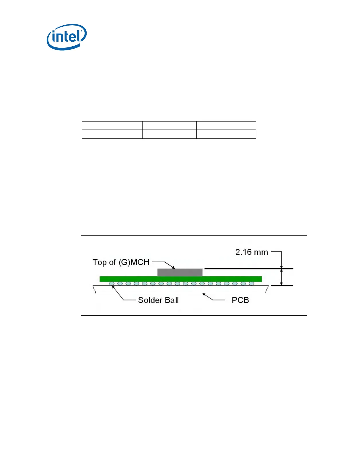
To ensure the package static load limit is not exceeded, the designer should
understand the post reflow package height. The following figure shows the nominal
post-reflow package height assumed for calculation of a heatsink clip preload of the
reference design. Refer to the package drawing in
Appendix B to perform a detailed
analysis.
Figure 2. Package Height
2.3 Thermal Specifications
To ensure proper operation and reliability of the (G)MCH, the case temperature must
be at or below the maximum value specified in
Table 2. System and component level
thermal enhancements are required to dissipate the heat generated and maintain the
(G)MCH within specifications. Chapter 3 provides the thermal metrology guidelines for
case temperature measurements.