Product Specifications
15 Thermal and Mechanical Design Guidelines
2.3.4 T
CONTROL
Limit
Intel
®
Quiet System Technology (Intel
®
QST) can monitor an embedded thermal
sensor. The maximum operating limit when monitoring this thermal sensor is T
CONTROL
.
For the (G)MCH this value is 99° C. This value should be programmed into the
appropriate register of Intel
®
QST, as the maximum sensor temperature for operation
of the (G)MCH.
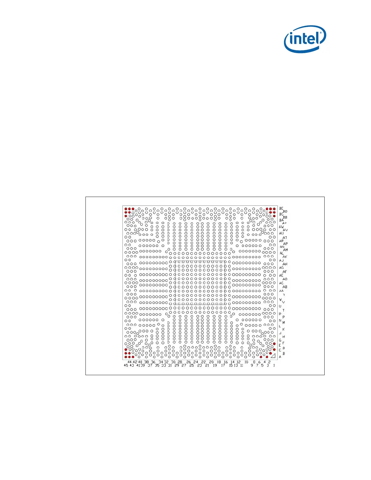
2.4 Non-Critical to Function Solder Balls
Intel has defined selected solder joints of the (G)MCH as non-critical to function
(NCTF) when evaluating package solder joints post environmental testing. The
(G)MCH signals at NCTF locations are typically redundant ground or non-critical
reserved, so the loss of the solder joint continuity at end of life conditions will not
affect the overall product functionality.
Figure 3 identifies the NCTF solder joints of
the (G)MCH package.
Figure 3. Non-Critical to Function Solder Balls
§