Reference Thermal Solution
27 Thermal and Mechanical Design Guidelines
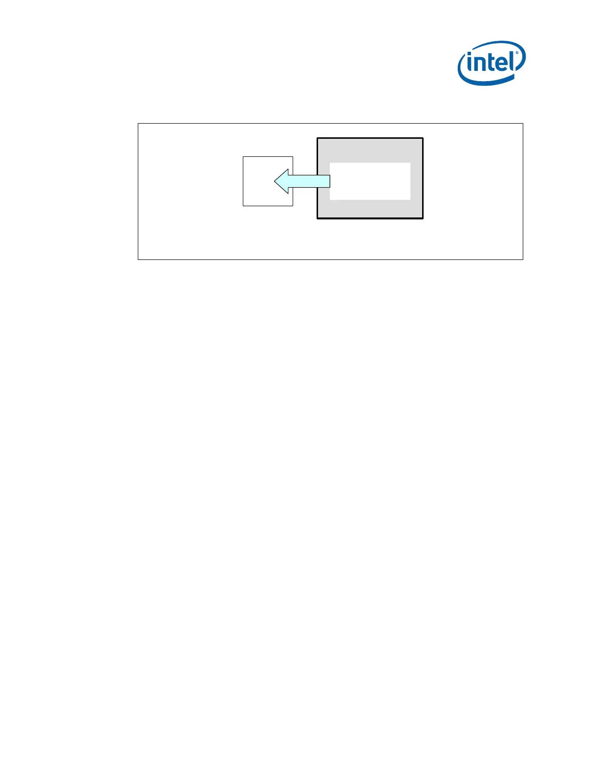
Figure 11. Processor Heatsink Orientation to Provide Airflow to (G)MCH Heatsink on a
Balanced Technology Extended (BTX) Platform
BTX Thermal
Module Assembly
over processor
Airflow Direction
GMCH
Top View
4.2 Reference Design Mechanical Envelope
The motherboard component keep-out restrictions for the (G)MCH on an ATX platform
are included in
Appendix B, Figure 15. The motherboard component keep-out
restrictions for the (G)MCH on a BTX platform are included in Appendix B, Figure 16.
4.3 Thermal Solution Assembly
The reference thermal solution for the (G)MCH for an ATX chassis is shown in
Figure 12 and is an aluminum extruded heatsink that uses two ramp retainers, a wire
preload clip, and four motherboard anchors. Refer to
Appendix B for the mechanical
drawings. The heatsink is attached to the motherboard by assembling the anchors into
the board, placing the heatsink, with the wire preload clip over the (G)MCH and
anchors at each of the corners, and securing the plastic ramp retainers through the
anchor loops before snapping each retainer into the fin gap. Leave the wire preload
clip loose in the extrusion during the wave solder process. The assembly is then sent
through the wave process. Post wave, the wire preload clip is snapped into place on
the hooks located on each of the ramp retainers. The clip provides the mechanical
preload to the package. This mechanical preload is necessary to provide both
sufficient pressure to minimize thermal contact resistance and improvement for solder
ball joint reliability. The mechanical stiffness and orientation of the extruded heat sink
also provides protection to reduce solder ball reliability risk. A thermal interface
material (Honeywell PCM45F) is pre-applied to the heatsink bottom over an area
which contacts the package die.
The design concept for the (G)MCH in a BTX chassis is shown in
Figure 13. The
heatsink is aluminum extruded and utilizes a Z-clip for attach. The clip is secured to
the system motherboard via two solder down anchors around the (G)MCH. The clip
helps to provide a mechanical preload to the package via the heatsink. A thermal
interface material (Honeywell PCM45F) will be pre-applied to the heatsink bottom over
an area in contact with the package die.
Note: To minimize solder ball joint reliability risk, the BTX Z-clip heatsink is intended to be
used with the Support Retention Mechanism (SRM) described in the Balanced
Technology Extended (BTX) Interface Specification. For additional information on
designing the BTX chassis to minimize solder ball joint reliability, refer to the Balanced
Technology Extended (BTX) Chassis Design Guide.