Thermal Metrology
19 Thermal and Mechanical Design Guidelines
3.2 Airflow Characterization
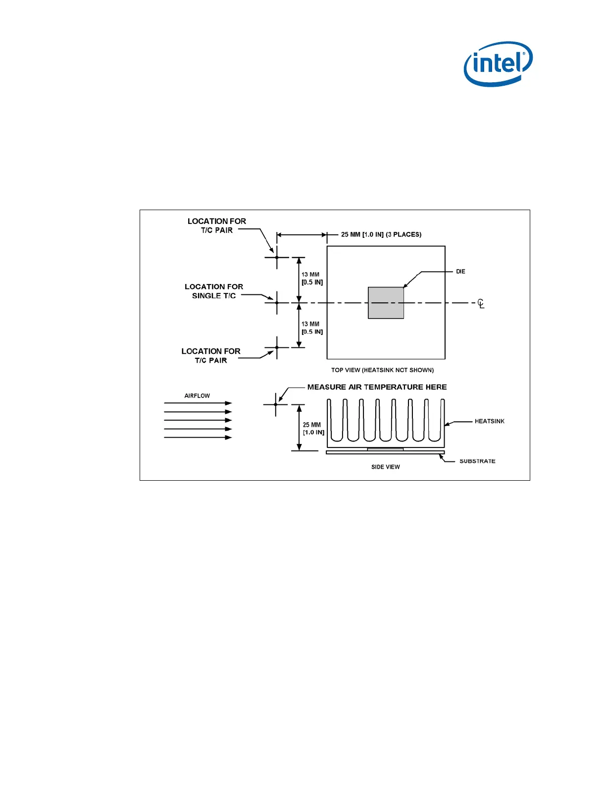
Figure 6 describes the recommended location for air temperature measurements
measured relative to the component. For a more accurate measurement of the
average approach air temperature, Intel recommends averaging temperatures
recorded from two thermocouples spaced about 25 mm [1.0 in] apart. Locations for
both a single thermocouple and a pair of thermocouples are presented.
Figure 6. Airflow &Temperature Measurement Locations
Airflow velocity can be measured using sensors that combine air velocity and
temperature measurements. Typical airflow sensor technology may include hot wire
anemometers.
Figure 6 provides guidance for airflow velocity measurement locations
which should be the same as used for temperature measurement. These locations are
for a typical JEDEC test setup and may not be compatible with chassis layouts due to
the proximity of the processor to the (G)MCH. The user may have to adjust the
locations for a specific chassis. Be aware that sensors may need to be aligned
perpendicular to the airflow velocity vector or an inaccurate measurement may result.
Measurements should be taken with the chassis fully sealed in its operational
configuration to achieve a representative airflow profile within the chassis.
§