Product Specifications
11 Thermal and Mechanical Design Guidelines
2 Product Specifications
2.1 Package Description
The (G)MCH is available in a 34 mm [1.34 in] x 34 mm [1.34 in] Flip Chip Ball Grid
Array (FC-BGA) package with 1254 solder balls. The die size is currently 10.80 mm
[0.425 in] x 9.06 mm [0.357 in] and is subject to change. A mechanical drawing of
the package is shown in
Figure 14, Appendix B.
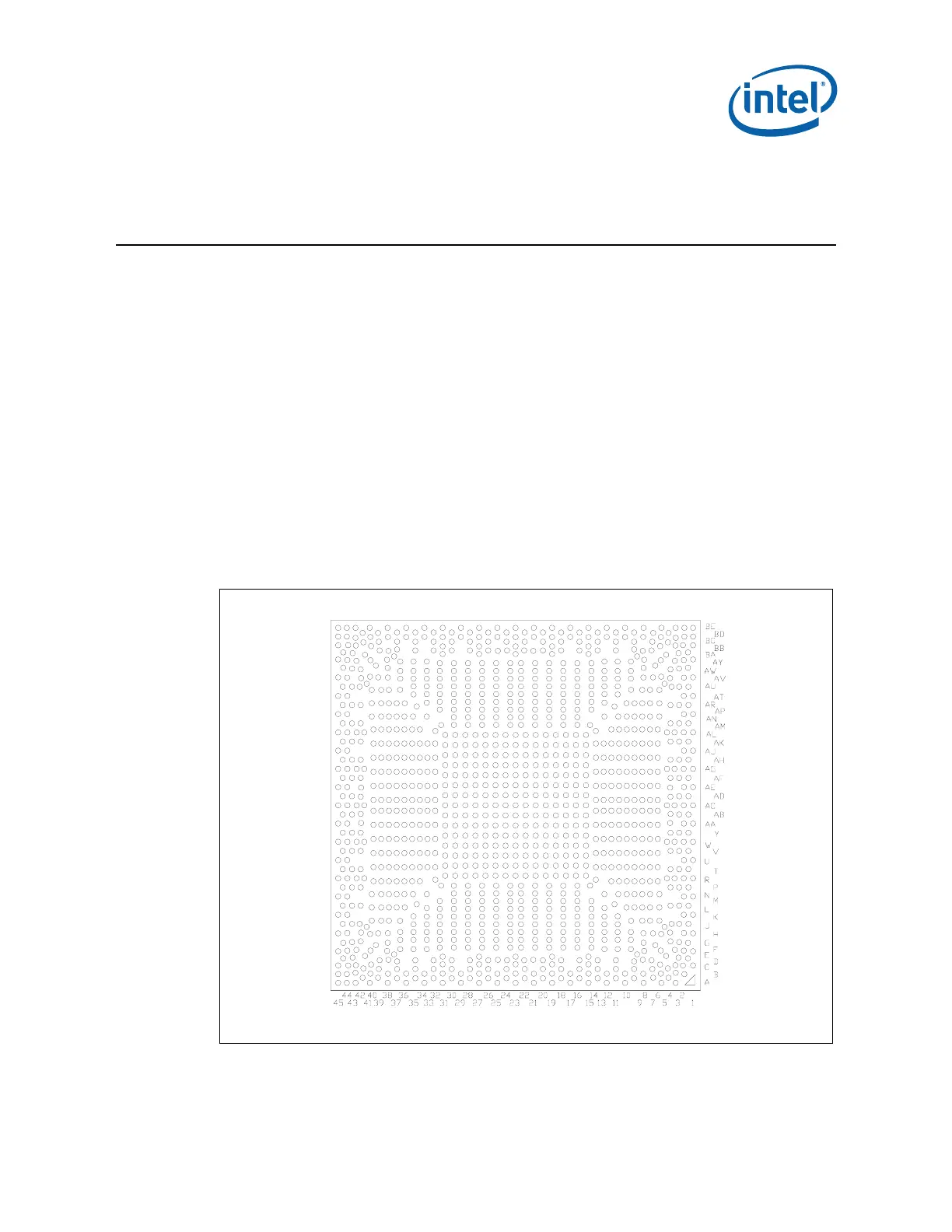
2.1.1 Non-Grid Array Package Ball Placement
The (G)MCH package utilizes a “balls anywhere” concept. Minimum ball pitch is
0.7 mm [0.028 in], but ball ordering does not follow a 0.7 mm grid. Board designers
should ensure correct ball placement when designing for the non-grid array pattern.
For exact ball locations relative to the package, refer to the Intel
®
4 Series Chipset
Family Datasheet.
Figure 1. (G)MCH Non-Grid Array
34 x 34mm Substrate [1.34 x 1.34 in]
Non-standard grid ball pattern. Minimum Pitch 0.7mm [0.028 in]