Reference Thermal Solution
Thermal and Mechanical Design Guidelines 22
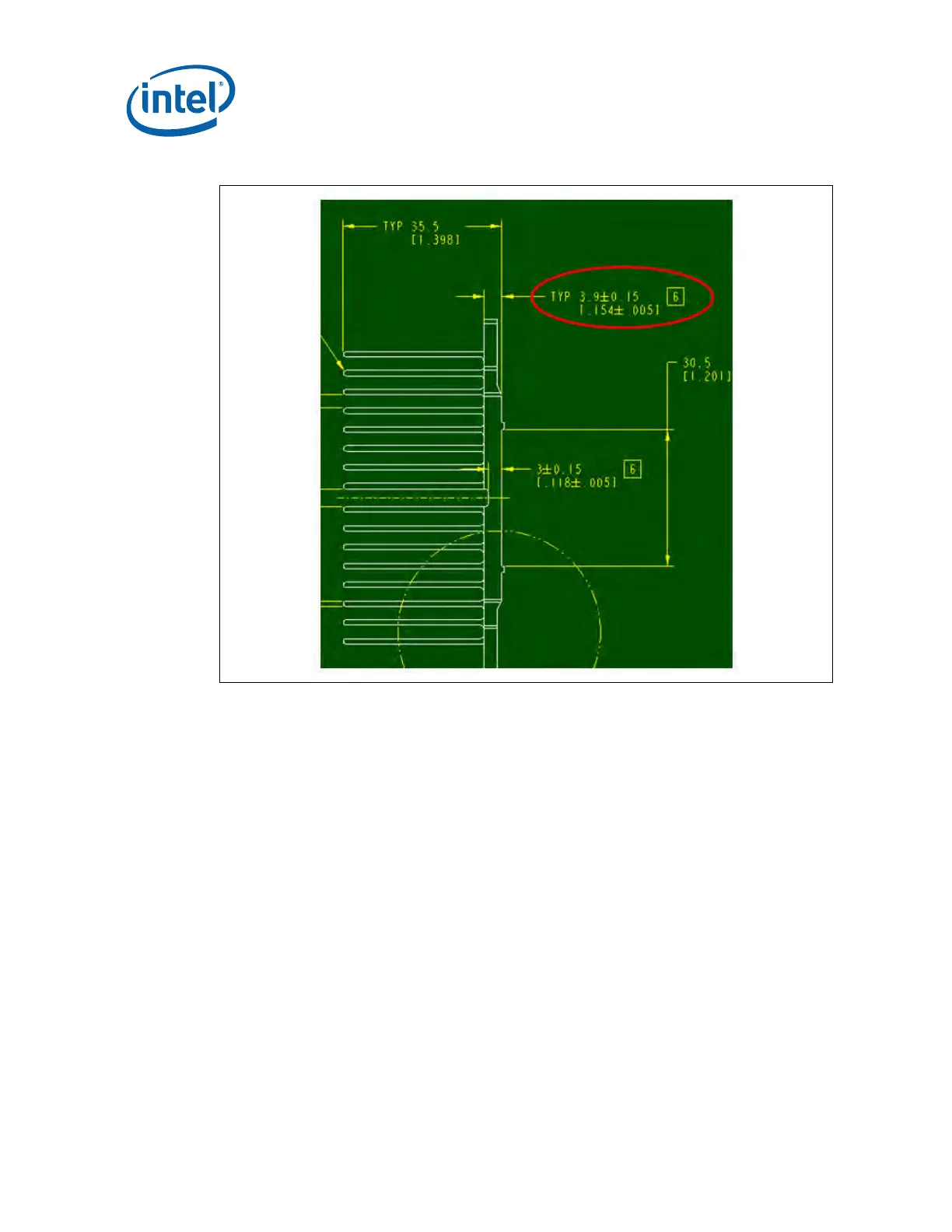
Figure 7. Cross-Cut Dimension Change of PWSHS Reference Design
The BTX reference design for the (G)MCH will reuse the Z-clip heatsink and MB
anchors from the Intel
®
3 Series Chipsets thermal solution. The thermal interface
material and extrusion design requirements are being evaluated for changes
necessary to meet the (G)MCH thermal requirements. The keep out zone remains the
same as used with the Intel
®
3 Series Chipsets, see Figure 16.
This chapter provides detailed information on operating environment assumptions,
heatsink manufacturing, and mechanical reliability requirements for the (G)MCH.
4.1 Operating Environment
The operating environment of the (G)MCH will differ depending on system
configuration and motherboard layout. This section defines operating environment
boundary conditions that are typical for ATX and BTX form factors. The system
designer should perform analysis in the expected platform operating environment to
assess impact on thermal solution selection.