Technical Reference
48
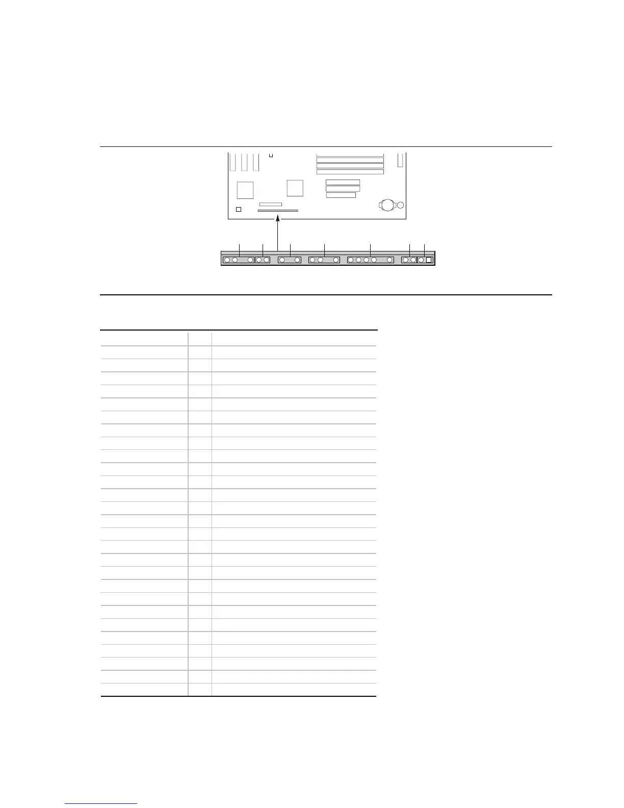
Front Panel Connectors
The motherboard has connectors for controls and indicators typically located on the front panel of
the computer.
OM05705
J9D1
27
1
24611162024 22
AB C D E FG
Table 30. Front Panel Connectors
Connector Pin Signal Name
A. Speaker* 27 SPKR_HDR
26 PIEZO_IN
25 Key
24 Ground
B. Reset switch 23 SW_RST
22 Ground
Key
C. Power LED 20 +5 V
19 Key
18 Ground
Key
D. Hard drive LED 16 +5 V
15 HD Active#
14 Key
13 +5 V
Key
E. Infrared 11 CONIR (consumer IR)
10 IrTX (transmit)
9 Ground
8 IrRX (receive)
7 Key
6 +5 V
Key
F. Sleep switch 4 +5 V
3 SLEEP
G. Power switch 2 Ground
1 SW_ON#
* A jumper on pins 26-27 enables the onboard speaker.