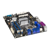
101
Figure 29. Removing the front plate by pressing the left and right plastic lids
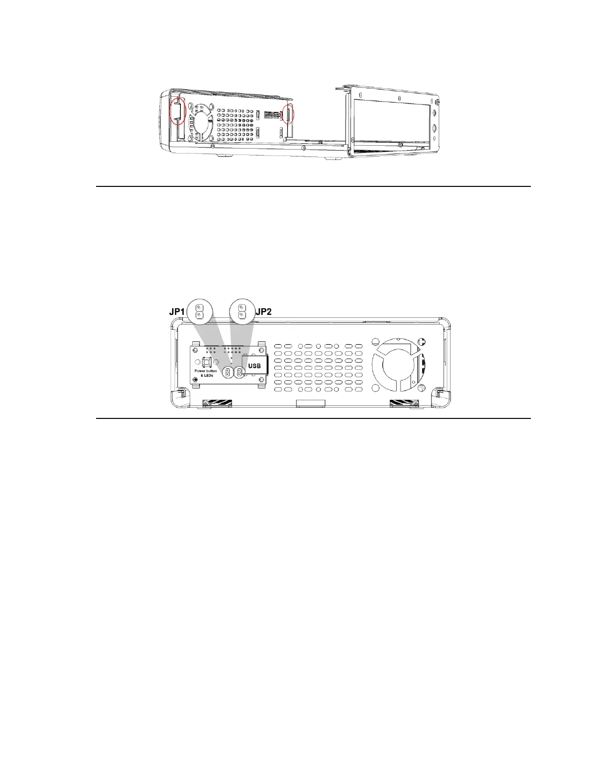
Near the front USB connector there are 2 jumpers (Figure 30) which are used to customize
how the board will start.
JP1: Disable On/Off power button (removing this jumper disables the power button).
Figure 30. JP1, JP2 pin header and 2 x USB slots
Front view of the enclosure, with the front plate removed.
After installing the desired USB devices, snap back the front plate.