EasyManuals Logo

Intel Celeron D User Manual

Intel Celeron D
64 pages
To Next Page IconTo Next Page
To Previous Page IconTo Previous Page
Page #54 background imageLoading...
Page #54 background image
54 Intel
®
Celeron
®
D Processor in the 775-Land LGA Package Thermal Design Guide
Order #303730
Case Temperature Reference Methodology
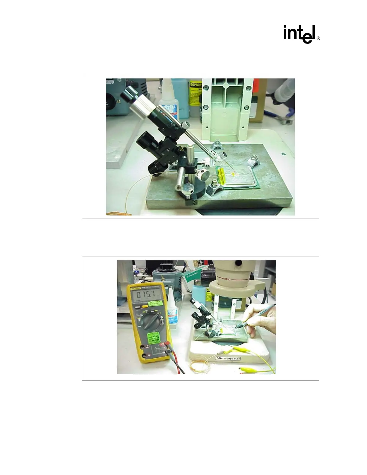
11. Measure resistance from thermocouple end wires (hold both wires to a DMM probe) to the
IHS surface. This should be the same value as measured during the thermocouple conditioning
step (Figure 29).
12. Place a small amount of Loctite* 498 adhesive in the groove where the bead is installed. Using
a fine point device, spread the adhesive in the groove around the needle, the thermocouple
bead and the thermocouple wires already installed in the groove during Step 5 above. Be
careful not to move the thermocouple bead during this step (Figure 30).
Figure 28. Using 3D Micromanipulator to Secure Bead Location
Figure 29. Measuring Resistance between Thermocouple and IHS

Table of Contents

Questions and Answers:

Question and Answer IconNeed help?

Do you have a question about the Intel Celeron D and is the answer not in the manual?

Intel Celeron D Specifications

General IconGeneral
Processor FamilyIntel Celeron D
ArchitectureNetBurst
Number of Cores1
SocketLGA 775
FSB Speed533 MHz
Operating Voltage1.25V-1.4V
Virtualization TechnologyNo
Integrated GraphicsNo
Core NamePrescott
Core SteppingD0
Clock Speed3.6 GHz
L1 Cache16 KB
Process Technology90 nm
Instruction SetSSE, SSE2, SSE3
L2 Cache256 KB - 512 KB

Related product manuals