Intel Desktop Board D975XBX2 Technical Product Specification
68
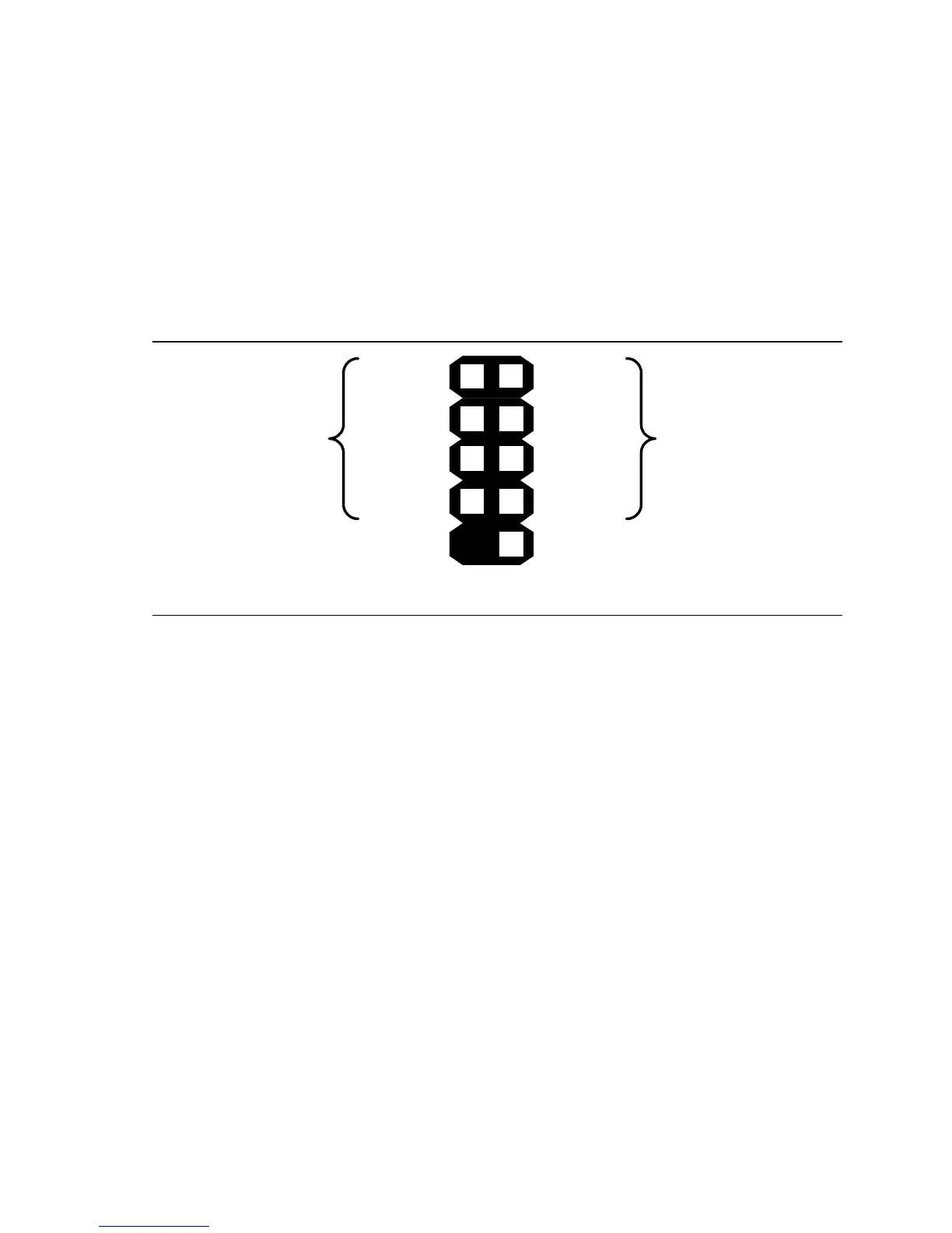
2.7.2.5 Front Panel USB Headers
Figure 22 is a connection diagram for the front panel USB headers.
#
INTEGRATOR’S NOTES
• The +5 V DC power on the USB headers is fused.
• Pins 1, 3, 5, and 7 comprise one USB port.
• Pins 2, 4, 6, and 8 comprise one USB port.
• Use only a front panel USB connector that conforms to the USB 2.0 specification for
high-performance USB devices.
OM18317
Key (no pin)
No connect
Power
(+5 V DC)
D-
D+
Ground
D+
Ground
D-
Power
(+5 V DC)
One
USB
Port
One
USB
Port
10
8
7
65
4
2
1
3
Figure 22. Connection Diagram for Front Panel USB Headers
 Loading...