41
Wiring
No. Type Function Notes
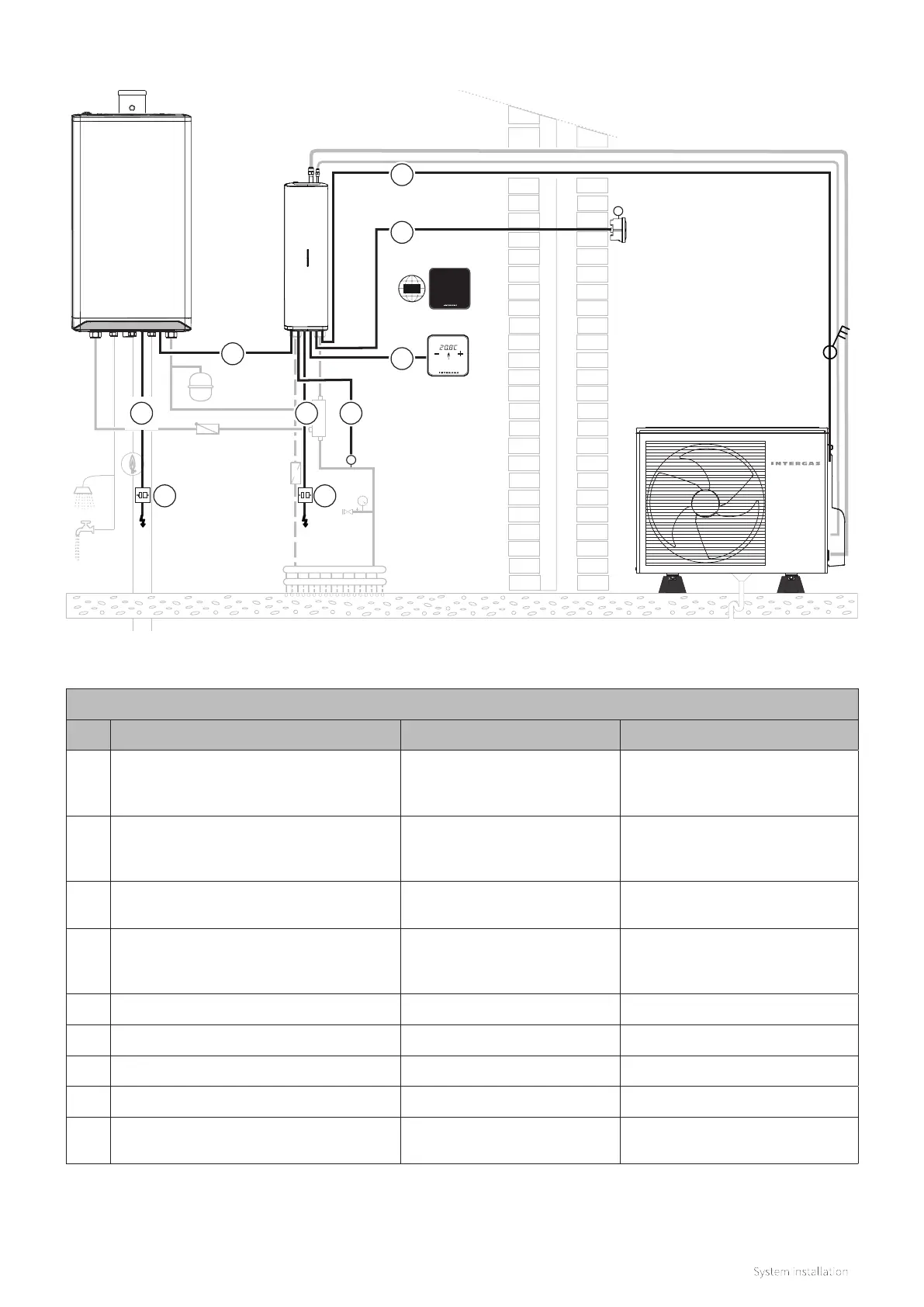
001 4 x 1.5 mm - Mains and switch live cable
Mains power and switched live
to the outdoor unit
Must be a 3 pole safe isolation
switch near to the outdoor unit.
See specification §3.1
002 2 x 0.8 mm - Signal cable External outdoor sensor T42
Optional for use with a weather-
dependent control setting. See
§8.8.6 and §11.5
003 2 x 0.8 mm - Signal cable Indoor temperature setpoint
Polarity not important when using
OpenTherm connectivity
004 2 x 0.8 mm - Signal cable
Remote flow temerature
sensor T43
Optional for use with a weather-
dependent control setting. See
§8.8.7 and §11.5
005 3 x 1.5 mm - Mains cable Indoor unit power supply 10 amp rated fuse 230V~ / 50Hz
006 2 x 0.8 mm - Signal cable Communication with boiler OpenTherm connectivity
007 3 x 0.75 mm - Mains cable Boiler power 3 amp rated fuse 230V~ / 50Hz
008 3 amp switched fused spur Power supply to boiler 230V~ / 50Hz
009 10 amp switched fused spur
Power supply to Indoor and
outdoor units
230V~ / 50Hz
8.7.2 Electrical installation overview
T
p
*
*
T
WWW
Remote flow temperature
sensor T43 (optional)
Thermostat
Gateway
Outdoor temperature
sensor T42 (optional)
3 pole isolator
switch
*
*
Components marked with an (*) are oered as optional accessories; see §3.2.
1
2
3
45
6
98
7