83
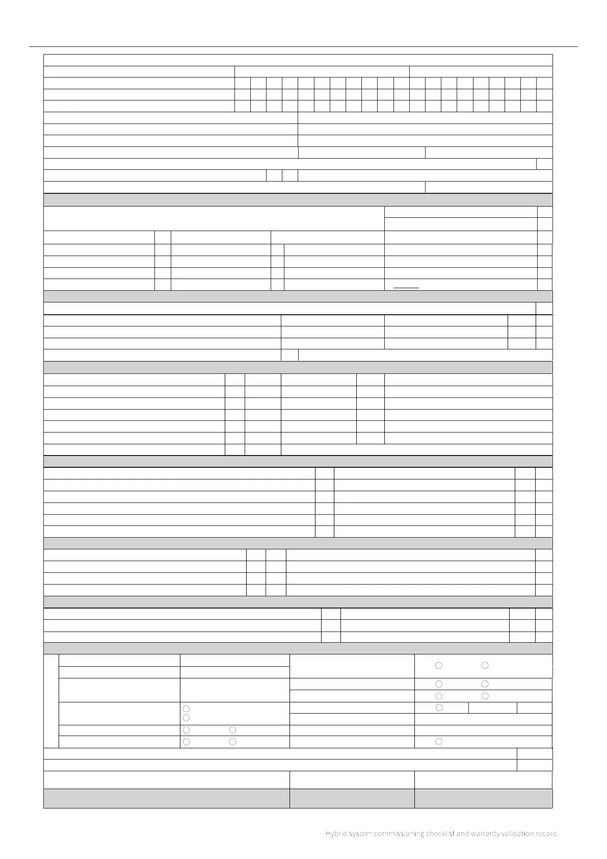
HYBRID SYSTEM COMMISSIONING CHECKLIST AND WARRANTY VALIDATION RECORD
Indoor unit serial number:
Outdoor serial number:
Commissioned by (PRINT NAME):
F-Gas / REFCOM registration number:
Company email:
Company address:
Commissioning date:
Does the outdoor unit location comply with current planning regulations? Yes
CONTROLS USED
Heating controls connected to the indoor unit
Load compensation
OpenTherm room thermostat
On/O room thermostat
WATER QUALITY
CENTRAL HEATING
°C
System correctly balanced?
Yes
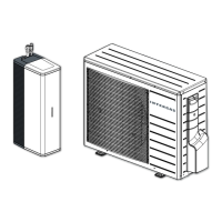
OUTDOOR UNIT
INDOOR UNIT
REFRIGERANT
INSTALLATION WIZARD
Record wizard settings
The manufacturers’ literature, including warranty checklist, has been explained and le with the customer
Commissioning Engineer’s signature
Customer’s signature
Have you completed the ENA application form (EVCP & HP Connections) with your local DNO (Distribution Network Operator) Approval number
Post code:
Has the installation been approved with local Building Control?
Intergas gateway fitted
Flue gas heat recovery (Boiler)
Post code:
Customer phone number:
Customer email address:
Outdoor sensor fitted
Outdoor sensor located on North facing wall
External flow sensor fitted
Radiators fitted
Radiators heatloss
Underfloor heatloss
Total heatloss
System water capacity
OpenTherm Make & model
Buer tank installed
Buer tank installed parallel
Buer tank in series
Buer tank capacity
Ltrs
Ltrs
Full flow L/P non return fitted to boiler return
System filter fitted to indoor unit return pipework
Make and model of system filter
Customer name and address:
Intergas system filter serial number:
Has the OD unit been installed on a level surface
Has the OD unit been installed over gravel to facilitate drainage
Has the OD unit been installed where it is protected from falling debris
Minimum distance from rear of unit
mm
Minimum distance from right side of unit
Minimum distance from le side of unit
mm
mm
Minimum distance below the unit
Minimum distance in front of the unit
mm
mm
mm
Has the OD unit been installed away from other heat sources
Has the OD unit been installed where it will not be subject to adverse weather conditions
Have the refrigerant lines been insulated correctly (inside and outside of property)
Have the refrigerant lines been protected with a proprietary cladding and secured correctly
Has the OD unit been installed with a 3 pole isolation switch near to the housing
Minimum distance in front of the unit
Minimum distance above the unit
Minimum distance below the unit
Minimum distance either side of the unit
mm
mm
mm
mm
The system has been flushed, cleaned and a suitable inhibitor added upon final fill, in accordance with BS7593 and our manufacturr's instructions.
Telephone number:Company name:
Underfloor heating
Weather compensation
App controlled thermostat
What system cleaner was used?
Brand:
Brand:
Product:
Product:
What inhibitor has been added to the system?
Central heating flow temperature
Central heating return temperature
°C
Yes
Dimensions of the OD the unit
Total length of refrigerant lines
mtrs
Recorded pressure of strength test for refrigerant lines
Recorded Vac pressure for refrigerant lines
bar
Micron
Recorded additional refrigerant (where applicable)*
grams
*Complete the field charge sticker and place it on outdoor unit, additional refrigerant must be recorded as per Article 6 of Regulation (EC) No 517/2014 commonly referred to
as the F-Gas regulations.
The operation of the Hybrid and system controls have been explained and demonstrated and understood by the customer
Yes
Yes
(To confirm satisfactory demonstration and receipt of manufacturers literature)
Signature
Signature
Print
Print
Insulation to refrigerant connections above the unit
Qty
Zones
What additional inhibitor has been used for low temperature protection?
Brand:
Product:
Qty Ltrs
Qty Ltrs
Qty Ltrs
Yes
Zone controls
Smart TRV's
PDHW
Cylinder NTC
kW
kW
kW
Running cost per hour = heater size (kW) x unit cost of electricity (kWh)
Low loss header connected to the unit 22mm flow
Water pressure reducing valve
Room thermostat:
Main heating system:
Maximum flow temperature of the
whole system (heat pump & boiler):
Boiler activation during heat
pump defrost cycle:
Connection of Xtend to boiler:
CH water flow temp sensor installed:
Boiler boost activation when
manually adjusting the thermostat:
Enable silent mode schedule:
Activat heat pump blockage schedule:
Bivalent mode & COP setting:
Boiler blocked above (˚C):
Heat pump is blocked under (˚C):
Current time format set:
˚C
Default 40 ˚C Minimum 30˚C Maximum 90˚c
Always (comfort)
Only at low water temperature
OpenTherm
On / O
Yes
No
Yes (Comfort)
No (Ecologic
Yes
No
Yes
No
˚C
˚C
Yes
Minimum 1.0 COP
Maximum 10.0 COP
COP setting
Standard
.
(Type)
(Rads/underfloor)
N/A Yes
Approved planning certification number: