46
8.8.2 Connector plug information
1. Isolate the power to the indoor unit by switching
o the fused spur and removing the 10amp fuse.
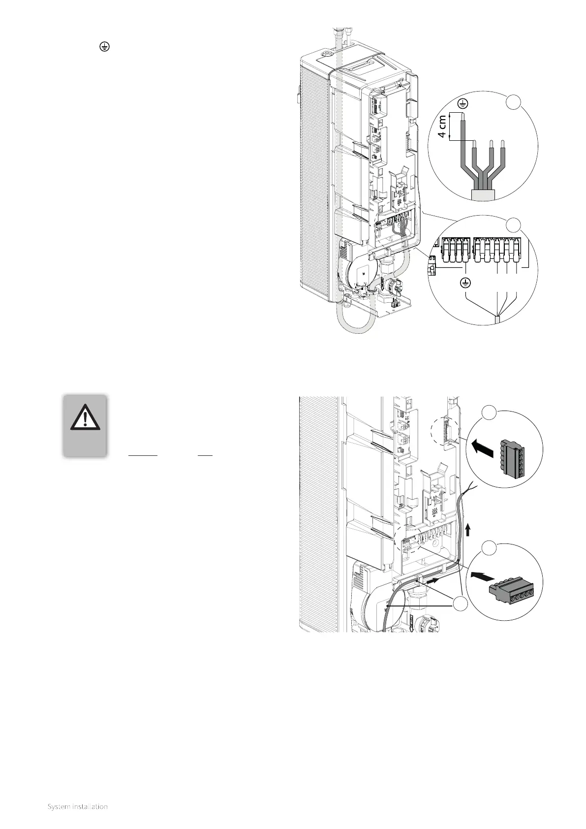
2. The included 5- and 6-pole plug-in connectors
must be attached to the power connectors; see (A)
and (B) in the adjacent illustration.
3. Use the cable tray on the housing of the printed
circuit board to guide the external wiring to the
relevant connector(s), see (C).
6-pin (X2)
5-pin (X13)
IMPORTANT
► For electrical safety please ensure
the supplied green connector plugs
are fitted correcty to X13 and X2
even if they are not to be used.
A
B
N
L’ 3
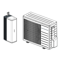
6. Cut the (N), (L) and (3*) wires to length noting that
the ( ) wire must be 4 cm longer; see diagram (A).
7. Remove 1 cm of insulation from all the wires.
8. Connect the wires to the terminal strip X1 and
Earth to X0 on the indoor unit; see diagram (B).
(3*) = Switched live supply from the indoor to
outdoor unit.
A
B
C