EasyManuals Logo

Interlogix Simon XT Installation Manual

Interlogix Simon XT
74 pages
To Next Page IconTo Next Page
To Previous Page IconTo Previous Page
Page #28 background imageLoading...
Page #28 background image
22 Simon XT Installation Manual
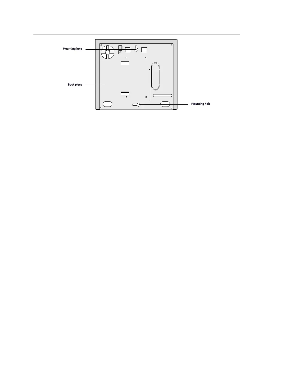
Figure 4: Panel mounting hole locations
5. Connect the chassis assembly to the mounted back piece and let it hang
down. This makes the terminal strip accessible for wiring various hardwired
components to the panel.
6. Feed wires through openings in the back piece to be ready to attach them to
the screw terminals or the phone connectors.
7. Install all screws and tighten gently.
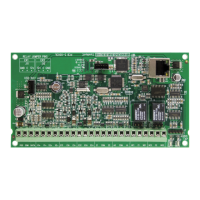
Connecting hardwired devices
The panel has seven screw terminals and two telephone connections (Figure 5
on page 23). The screw terminals connect AC power, sirens, and/or hardwired
detectors.
Program sensors and devices before you install them. Follow the instructions in
to add the sensors to panel memory.

Other manuals for Interlogix Simon XT

Questions and Answers:

Question and Answer IconNeed help?

Do you have a question about the Interlogix Simon XT and is the answer not in the manual?

Interlogix Simon XT Specifications

Power IconPower
power requirements6V nominal
standby current30mA (10mA in PowerSave Mode)
peak current1.7 A
Operating Environment IconOperating Environment
operating temperature32 to 120°F (0 to 49°C)
storage temperature-30 to 140°F (-34 to 60°C)
max. relative humidity90% non-condensing
Dimensions IconDimensions
height4 1/16 in.
width1 7/8 in.

Related product manuals