EasyManuals Logo

Interlogix TruVision 6 Series User Manual

Interlogix TruVision 6 Series
84 pages
To Next Page IconTo Next Page
To Previous Page IconTo Previous Page
Page #49 background imageLoading...
Page #49 background image
Installation Guide 45
access for the cables that will be connected to the
camera.
Black rubber insert
Note:
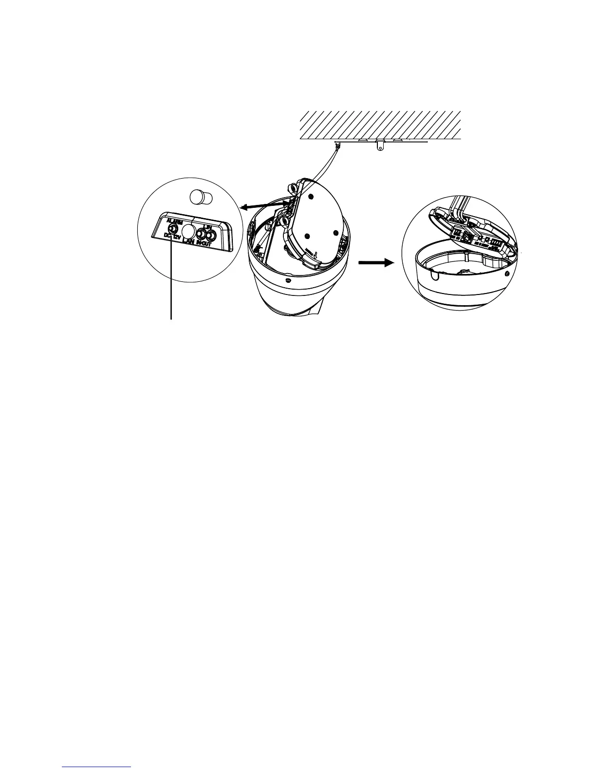
When routing the cables, remove the whole rubber
sealing, then remove the sealing pillar, and then insert
the wire. Otherwise, keep the sealing plug intact.
5. Once all the cable connections are made, lower the
access cover and tighten the Torx screws. Line up the
turret with the mounting plate, there is an arrow and the
word FRONT referenced on the turret base and mounting
plate. Line up the three Phillips screws that are located
on the access cover with the three slots in the adapter
plate. Rotate the turret clockwise as far is the turret will
travel. Tighten the locking Torx screw at the base of the
turret.

Questions and Answers:

Question and Answer IconNeed help?

Do you have a question about the Interlogix TruVision 6 Series and is the answer not in the manual?

Interlogix TruVision 6 Series Specifications

General IconGeneral
BrandInterlogix
ModelTruVision 6 Series
CategoryIP Camera
LanguageEnglish

Related product manuals