14
Version 1.1 (11/2011) en
Original language
Product information
9006 Hybrid Control for RollerDrive
DIP switches
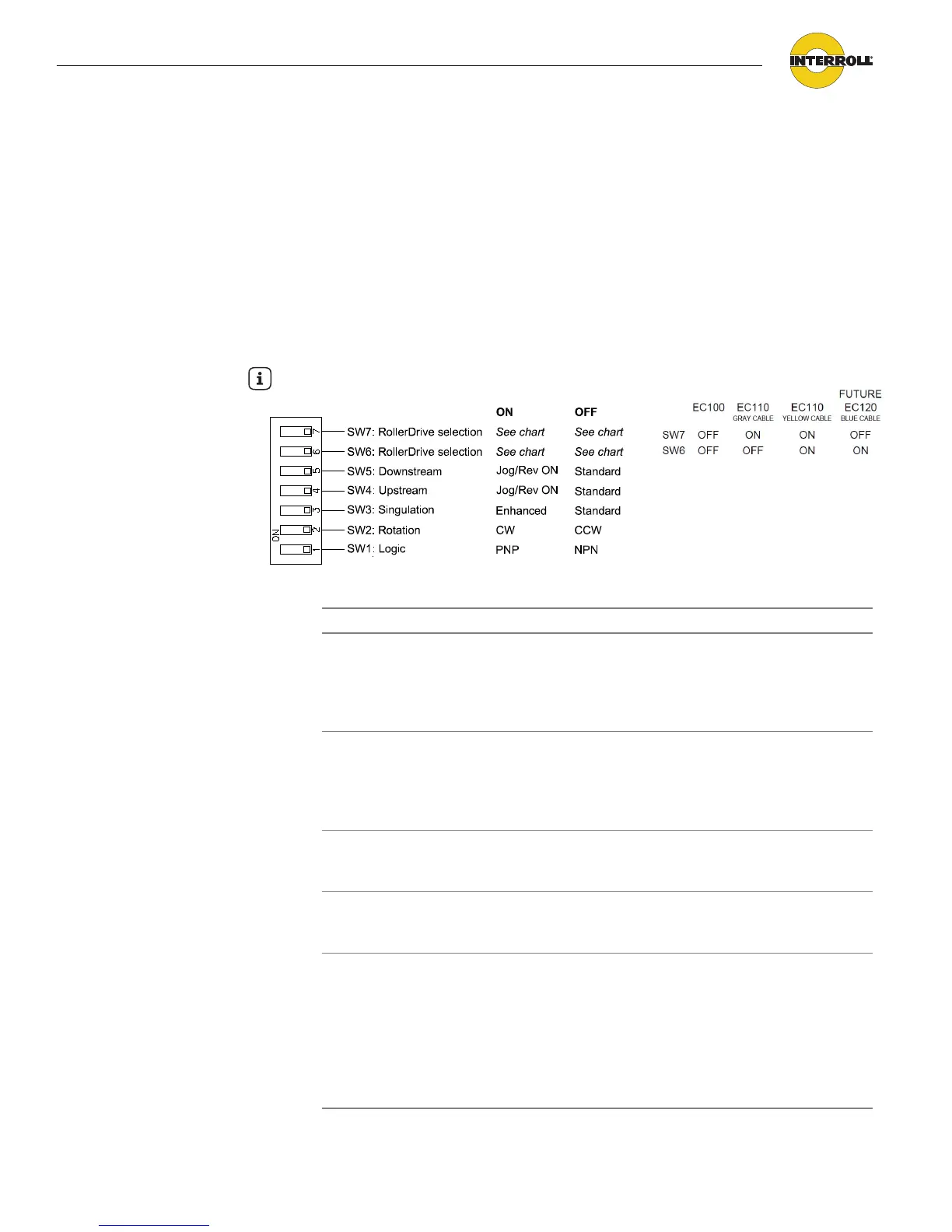
The DIP switches allow the selection of various types of control operations. The
default DIP switch settings are all OFF. This would provide:
• RollerDrive selection of an EC100 (SW6, SW7)
• Standard 9006 connectivity upstream and downstream (SW4, SW5)
• Standard singulate mode (SW3)
• Motor running counter clockwise (SW2)
• All NPN inputs and outputs (SW1)
The following table shows the switch position for different situations:
Hint
DIP switch settings are read at reset (power-up) only.
DIP switch ON (up position OFF (down position)
SW5
Downstream
Jog/Rev ON: the downstream
peer-to-peer cable is connected
to another 9006 and
the jog/reverse signal is
transmitted
Standard: the jog/reverse
signal is not transmitted
SW4
Upstream
Jog/Rev ON: the upstream
peer-to-peer cable is connected
to another 9006 and
the jog/reverse signal is
transmitted
Standard: the jog/reverse
signal is not transmitted
SW3
Singulation
Enhanced: enhanced
singulated release (see
"Glossary", page 47) is needed
Standard: singulated release
(see "Glossary", page 47) is
needed
SW2
Rotation
Clockwise: (rotation of the
RollerDrive seen from the cable
end)
Counter clockwise: (rotation
of the RollerDrive seen from
the cable end)
SW1
Logic
PNP: all external inputs,
photoeye inputs and outputs
are active high (24 VDC)
NPN: all external inputs,
photoeye inputs and outputs
are active low (0 VDC
ground).
This excludes the "No fault
output" which is always active
high (+24 VDC) when in either
NPN or PNP mode.