34
12.0 checks and repair work at electronics
12.1 Main module
• The main module is maintenance-free. Only basical checks
can be done.
• The module is mounted at back of chassis in front of the
backwheels.
• Before control you must secure that the batteries are
loaded.
Status display
For a simple visual assessing of defects the module is equipped with
a green light diode for status display.
Check of status display:
• Swith on wheelchair at remote.
• Check light diode (see index below).
• Status display lightens?
• Status display off?
• Status display flashes?
> Module is in order.
> Check voltage supply of
module.
Check programming.
> Replace module.
Check Action
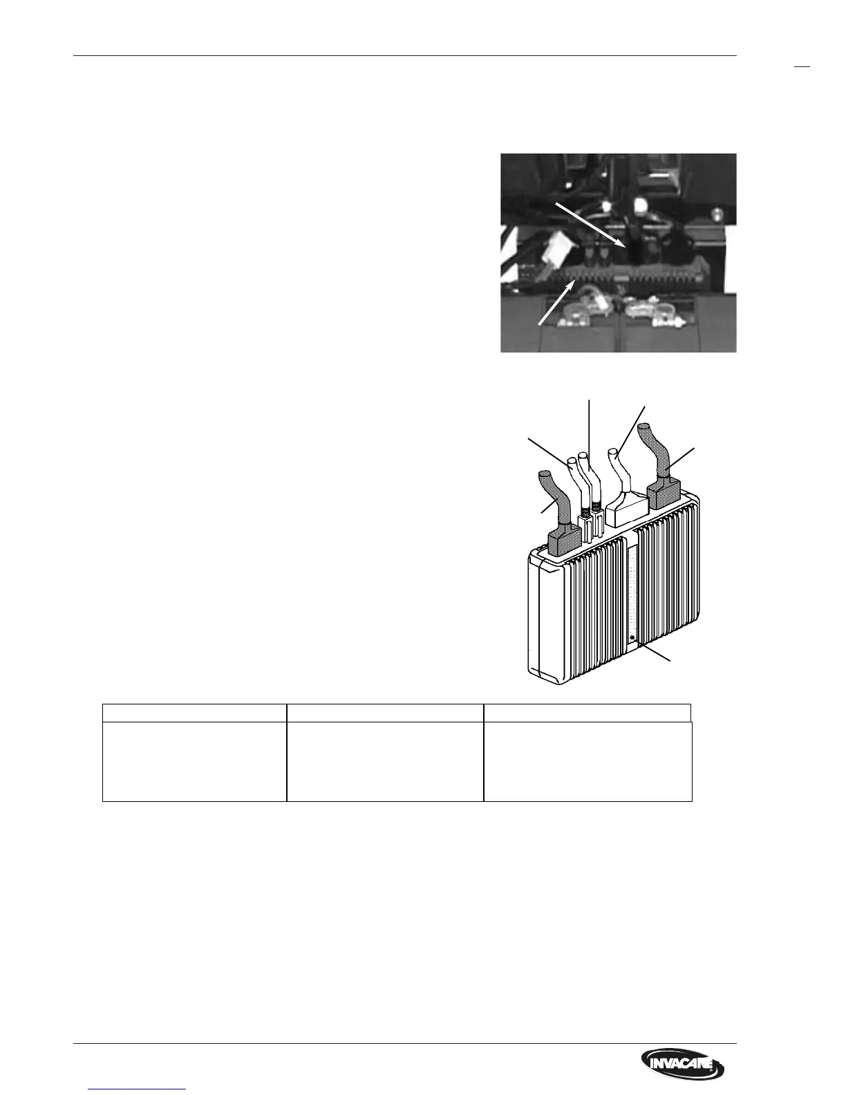
Check voltage supply to main module
• Bring seat system in service position and arrest.
• Draw off plug of batterycable out of main module.
• Measure voltage at contacts of batteryplug.
Both left contact pins are connected with the positive pole, both
right contact pins are connected with the negative pole of battery.
The voltage must be at least 19 V.
Trouble
• Voltage under 19 V?
• No voltage?
Action
> Pre-charge battery.
See chapter 10.2.
> Replace battery.
> Replace cable.
Cause
- Batteries deep dis-
charged.
- Cable defective.
Disassembly
• Bring seat system in service position and arrest.
• Mark plugs and draw off from main module.
• Release both cross slotted screws of module.
Screws are accessible from rear of wheelchair (bot-
tom).
• Remove module.
• If necessary release the voltage supply cable from
batteries, remove batteries (see chapter 10.1).
Release cable socket at battery box and replace
cable completely.
NOTE:
• Secure that all plugs are clicked in correctly.
Status display
Motorcable
Main module, serviceview
Main module
Main module
Plug
Motor-
cable
Remotecable
Light-/servo-
module cable
Batterycable
Trouble index for main module
Assembly
• Assembly is carried out in reverse order.
Batteries