SECTION 5—WHEELCHAIR OPERATION
TDX™ Wheelchairs 64 Part No 1114809
Battery Gauge Display (BGD)
Located at the rear of the joystick housing, the BGD provides information on the
remaining charge in the batteries. At full charge, all six segments of the bar graph are lit.
As the battery discharges, the farthest right segment will go out until only the red bar is
lit. At this level, the last red bar will start to flash on and off to indicate that the user
should charge the batteries as soon as possible.
The BGD also serves as a system diagnostic device when a fault is detected by the control
module. A specific number of flashes of the last two red bars (up to eight flashes)
separated by a pause will indicate the type of fault detected. This information is useful to
a qualified technician when making repairs or reprogramming the electronics.
MPJ Joystick Switches and Indicators
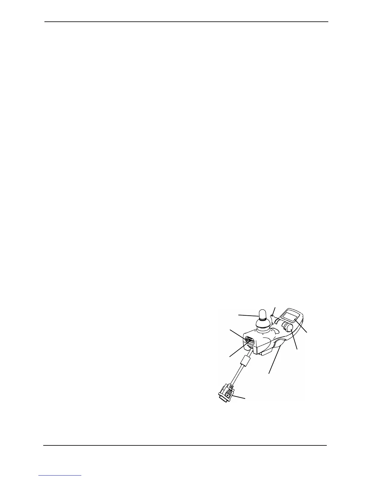
NOTE: For this procedure, refer to FIGURE 5.7 and FIGURE 5.8 on page 66.
NOTE: The MPJ joystick must be used with the MK5 EX controller.
Drive Select Toggle Switch
The drive select toggle switch is located on the left side, below the LCD. The drive select
position is momentary, meaning that it will return to the neutral position after a selection
is made.
This switch allows the operator to select the type of operation or performance which best
suits a particular control need or situation. The DRIVE 1 program uses performance
values which are independent of those used for the DRIVE 2 or 3 or 4 program. As an
example, an operator may have a control need for spasticity in the morning and a very
different need in the afternoon. DRIVE 1 can be programmed for higher speeds and
quicker response while DRIVE 2 can be programmed for slower speeds and less
responsiveness or vise versa. The other two drive programs could be indoor and outdoor
versions of DRIVE 1 and DRIVE 2.
Selecting the Drive Mode
1. Move the toggle up and release. DRIVE
1 will appear on LCD.
2. Move the toggle up and release again.
DRIVE 2 will appear on LCD.
3. Move the toggle up and release again.
DRIVE 3 will appear on LCD.
4. Move the toggle up and release again.
DRIVE 4 will appear on LCD.
5. Move the toggle up and release one
more time to select DRIVE 1.
FIGURE 5.7 MPJ Joystick Switches and
Indicators
Joystick
Remote
On/Off
Input
Optional
Drive
Select
Input
To Controller
Drive Select Toggle Switch
LCD
Speed
Control
Knob
Charger/
Programming Input




 To Next Page