Optidrive HVAC User Guide V2.00
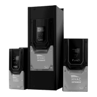
3.7. Guidelines for mounting IP55 Units
Before mounting the drive, ensure that the chosen location meets the environmental condition requirements for the drive shown in
section 11.1
The drive must be mounted vertically, on a suitable flat surface
The minimum mounting clearances as shown in the table below must be observed
The mounting site and chosen mountings should be sufficient to support the weight of the drives
IP55 units do not require mounting inside an electrical control cabinet; however they may be if desired.
Typical drive heat losses are 3% of operating load
conditions.
Above are guidelines only and the operating ambient
temperature of the drive MUST be maintained at all
times.
Using the drive as a template, or the dimensions shown above, mark the locations required for drilling
Suitable cable glands to maintain the IP protection of the drive are required. Gland sizes should be selected based on the number
and size of the required connection cables. Drives are supplied with a plain, undrilled gland plate to allow the correct hole sizes to
be cut as required. Remove the gland plate from the drive prior to drilling.
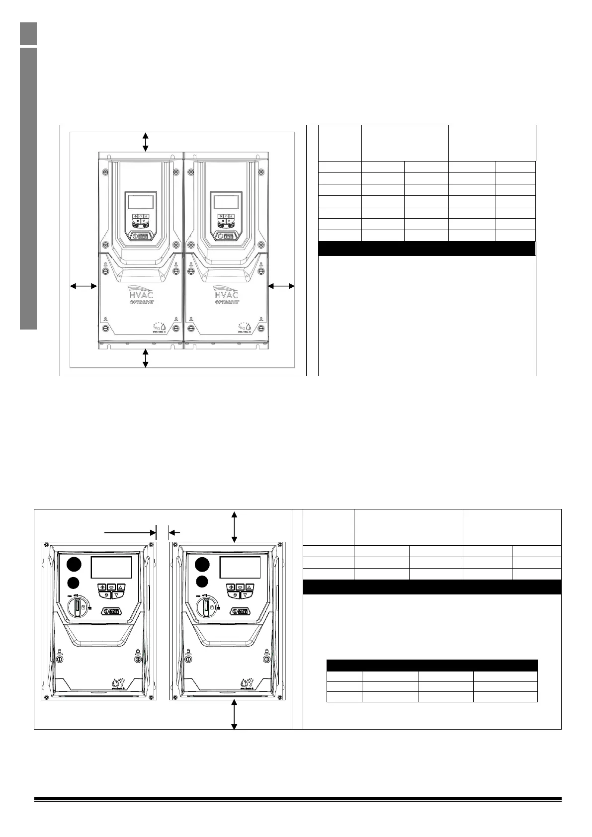
3.8. Guidelines for mounting (IP66 Units)
Before mounting the drive, ensure that the chosen location meets the environmental condition requirements for the drive shown in
section 11.1
The drive must be mounted vertically, on a suitable flat surface
The minimum mounting clearances as shown in the table below must be observed
The mounting site and chosen mountings should be sufficient to support the weight of the drives
Typical drive heat losses are approximately 3% of operating load
conditions.
Above are guidelines only and the operating ambient temperature
of the drive MUST be maintained at all times.
Using the drive as a template, or the dimensions shown above, mark the locations required for drilling
Suitable cable glands to maintain the ingress protection of the drive are required. Gland holes for power and motor cables are pre-
moulded into the drive enclosure, recommended gland sizes are shown above. Gland holes for control cables may be cut as
required.
 Loading...


