Do you have a question about the Invertek Drives Optidrive Series and is the answer not in the manual?
Crucial safety warnings and precautions for drive installation and operation.
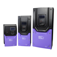
Details on various drive models and their specifications, including frame sizes and ratings.
Specifications and model numbers for IP66 enclosed drive units.
Specifications and model numbers for IP55 enclosed drive units.
Guide to interpreting the drive's model number to understand its features and options.
Specific mechanical dimensions and weight details for IP20 enclosed units.
Specific mechanical dimensions and weight details for IP55 enclosed units.
Specific mechanical dimensions and weight details for IP66 enclosed units.
Recommendations for mounting IP20 drives within control cabinets, including air gaps.
Step-by-step instructions for physically mounting IP20 drives, including screw and DIN rail methods.
Guidelines for mounting IP55 drives, focusing on clearances and gland plate usage.
Guidelines for mounting IP66 drives, including clearances and gland plate usage.
Procedures for performing routine checks and maintenance on the drive to ensure optimal operation.
Essential guidelines for proper grounding of the drive for safety and EMC compliance.
Specific grounding recommendations to achieve optimal EMC performance.
Detailed guidelines for connecting ground terminals and ensuring proper ground loop impedance.
Specifies requirements for the protective earth conductor's cross-sectional area.
Guidance on connecting the drive's safety ground to the building's grounding system.
Instructions for connecting the motor's ground to the drive's ground terminal.
Information on leakage current and requirements for using ELCBs with the drive.
Proper methods for terminating motor cable shields for EMC compliance.
Details on connecting single-phase and three-phase AC supply power to the drive.
Guidelines for connecting the drive to the motor, including cable types and insulation considerations.
Explains how to connect motor windings (Star or Delta) based on voltage ratings.
Information on the drive's built-in thermal overload protection for the motor.
How to connect a motor thermistor for temperature monitoring and protection.
Guidelines for wiring analog and digital control signals to the drive terminals.
Visual diagrams illustrating power and control terminal connections for the drive.
Describes the layout and functions of the 7-segment LED keypad on IP20 drives.
Step-by-step procedure for changing drive parameters using the LED keypad.
Describes the OLED keypad layout and functions for IP55 and IP66 drives.
Step-by-step procedure for accessing and changing parameters using the OLED keypad.
Procedure to reset all drive parameters back to their factory default settings.
How to save current parameter settings as user defaults for quick restoration.
How to switch between local (Hand) and remote (Auto) control modes using the keypad.
Crucial step to input motor rated voltage, current, frequency, and speed for optimal operation.
How to set the drive's minimum and maximum operating speed limits.
Configuration of ramp times for smooth acceleration and deceleration of the motor.
Choosing between ramp-to-stop or coast-to-stop behavior when the drive is disabled.
Configuration of fundamental drive parameters including speed, ramps, and motor data.
Selects the primary method for controlling the drive (terminals, keypad, fieldbus, etc.).
Configures the function assigned to each of the drive's digital inputs.
Detailed table mapping digital input functions to terminal connections and parameter settings.
Covers advanced parameters like preset speeds, skip frequencies, and analog output functions.
Configures the function assigned to Relay Output 1, determining its activation logic.
Configures the function assigned to Relay Output 2, determining its activation logic.
Configures the drive's output switching frequency, affecting motor noise and efficiency.
Configures the input format (voltage/current, uni/bi-polar) for Analog Input 1.
Scales the analog input signal applied to Analog Input 1 to a usable range.
Adjusts the offset value for the Analog Input 1 signal to compensate for sensor variations.
Initiates an auto-tune process to measure motor parameters for optimal control.
Configuration settings for serial communication protocols like Modbus RTU and BACnet.
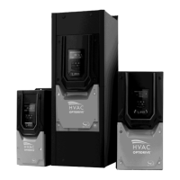
Parameters specific to HVAC applications, such as pump staging and fire mode.
Enables and configures the pump staging (cascade) function for multiple pumps.
Lists the last four recorded fault codes for diagnostic purposes.
Details on connecting and communicating with the drive using the Modbus RTU protocol.
Lists accessible Modbus registers for controlling and monitoring the Optidrive HVAC.
Provides output current ratings, fuse/MCB recommendations, and cable sizes for different models.
Information on when and how to apply derating factors for output current capacity.
A guide to interpreting fault codes, their descriptions, and recommended corrective actions.
| Category | Variable Frequency Drive (VFD) |
|---|---|
| Output Voltage Range | 0 to Input Voltage |
| Control Method | Sensorless Vector Control |
| Overload Capacity | 150% for 60 seconds |
| Braking | Dynamic braking |
| Protection | Overcurrent, overvoltage, undervoltage, overload, short circuit, ground fault, overheating |
| Communication | Modbus RTU, Ethernet, CANopen, Profibus |
| Enclosure | IP20 |
| Operating Temperature | -10°C to +50°C (Derating may apply at higher temperatures) |
| Humidity | Up to 95% non-condensing |
| Cooling Method | Fan cooled |