Optidrive HVAC User Guide V2.00
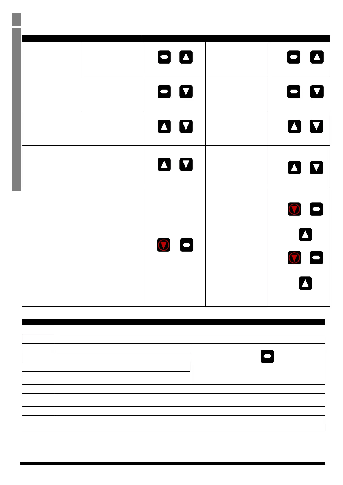
5.3. Advanced Keypad Operation Short Cuts – Standard LED Keypad (IP20 Drives)
Fast Selection of
Parameter Groups
Note : Parameter Group
Access must be enabled
P1-14 = 101
The next highest
Parameter group is
selected
Display shows
Press +
Display shows
The next lowest
Parameter group is
selected
Display shows
Press +
Display shows
Select lowest Group
Parameter
The first parameter of a
group is selected
Display shows
Press +
Display shows
Set Parameter to
minimum value
Any numerical value
(Whilst editing a
parameter value)
The parameter is set to
the minimum value
When editing P1-01
Display shows .
Press +
Display shows.
Adjusting individual
digits within a parameter
value
Any numerical value
(Whilst editing a
parameter value)
Individual parameter
digits can be adjusted
When editing P1-10
Display shows
Press +
Display shows
Press
Display shows
Press +
Display shows
Press
Display shows
Etc...
5.4. Drive Operating Displays – Standard LED Keypad (IP20 Drives)
Drive mains power applied, but no Enable or Run signal applied
Motor Autotune in progress.
Drive running, display shows output frequency (Hz)
Whilst the drive is running, the following displays can be
selected by briefly pressing the button on the drive.
Each press of the button will cycle the display through to the
next selection.
Drive running, display shows motor current (Amps)
Drive Running, display shows motor power (kW)
Drive Running, display shows customer selected units, see
parameters P2-21 and P2-22
Drive mains power not present, external 24 Volt control power supply present only
Output power hardware enable circuit open. External links are required to the STO inputs (terminals 12 and 13) as shown in
section 4.8 Connection Diagram
Parameters reset to factory default settings
Parameters reset to User default settings
For drive fault code displays, refer to section 12.1
 Loading...


