Optidrive HVAC User Guide V2.00
4.7. Control Terminal Wiring
All analog signal cables should be suitably shielded. Twisted pair cables are recommended.
Power and Control Signal cables should be routed separately where possible, and must not be routed parallel to each other
Signal levels of different voltages e.g. 24 Volt DC and 110 Volt AC, should not be routed in the same cable.
Maximum control terminal tightening torque is 0.5Nm
Control Cable entry conductor size: 0.05 – 2.5mm
2
/ 30 – 12 AWG.
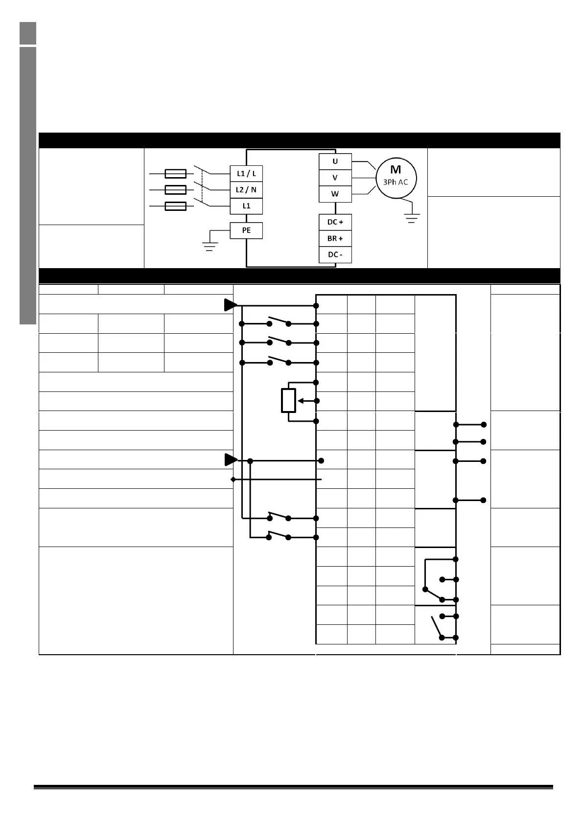
4.8. Connection Diagram
4.8.1. Power Terminal Designations
Incoming Mains Power
Supply
For 1 Phase Supply, connect
to L1/L and L2/N terminals.
For 3 Phase Supply, connect
to L1, L2 & L3 terminals.
Phase sequence is not
important.
Motor Connections
Connect the motor to the U, V & W
terminals.
The motor earth must be connected
to the drive
Protective Earth / Ground
connection.
The drive must be Earthed /
Grounded
4.8.2. Control Terminal Connections & Factory Settings
+24V Supply (100mA) / External Input
Digital Inputs : 8 – 30 Volt DC
+ 10 Volt, 10mA Output
Analog Output : 0 – 10 Volt / 4-20mA, 20mA Max
0 Volt Supply / External Input
Analog Output : 0 – 10 Volt / 4-20mA, 20mA Max
External Hardware Enable Circuit
Relay Contacts
250VAC / 30VDC
5A Maximum
 Loading...


