Goodrive350 series high-performance multi-function inverter Chapter 6
-155-
Detailed parameter description
29: STO action
48–63: Reserved
Output terminal
polarity selection
This function code is used to set the polarity of
output terminals.
When the bit is set to 0, input terminal polarity is
positive;
When the bit is set to 1 input terminal polarity is
negative.
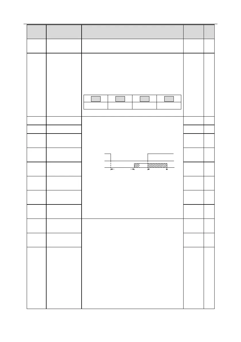
This function code defines the corresponding delay
of the level variation from switch-on to switch-off.
Y electric level
Y valid
Invalid
Switch on
delay
invalid
Valid
Switch off
delay
Setting range: 0.000–50.000s
Note: P06.08 and P06.09 are valid only when
P06.00=1.
Relay RO1
switch-on delay
Relay RO1
switch-off delay
Relay RO2
switch-on delay
Relay RO2
switch-off delay
10: AI1 input value
11: AI2input value
12: AI3 input value
13: Input value of high-speed pulse HDIA
14: Set value 1 of MODBUS communication
15: Set value 2 of MODBUS communication
16: Set value 1 of PROFIBUS\CANopen
communication
17: Set value 2 of PROFIBUS\CANopen
communication
18: Set value 1 of Ethernet communication
19: Set value 2 of Ethernet communication
20: Input value of high-speed pulse HDIB
HDO high-speed
pulse output

 Loading...


