Goodrive350 series high-performance multi-function inverter Chapter 6
-156-
Detailed parameter description
21: Reserved
22: Torque current (bipolar, 100% corresponds to
10V)
23: Exciting current (100% corresponds to 10V)
24: Set frequency (bipolar)
25: Ramps reference frequency (bipolar)
26: Running speed (bipolar)
27: Reserved
28: C_AO1 from CODESYS (set P27.00 to 1)
29: C_AO2 from CODESYS (set P27.00 to 1)
30–47: Reserved
Lower limit of
AO1 output
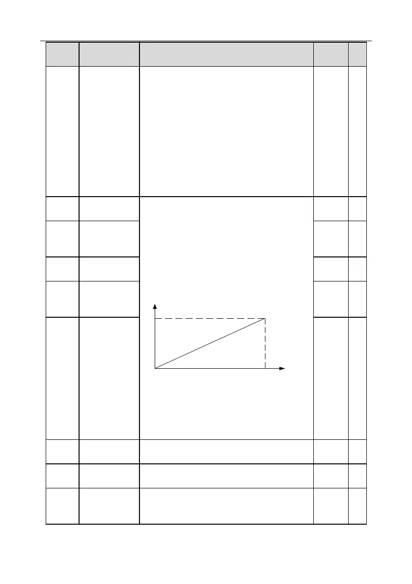
Above function codes define the relation between
output value and analog output. When the output
value exceeds the set max./min. output range, the
upper/low limit of output will be adopted during
calculation.
When analog output is current output, 1mA
corresponds to 0.5V voltage. In different
applications, 100% of output value corresponds to
different analog outputs.
Setting range of P06.17: -100.0%–P06.19
Setting range of P06.18: 0.00V–10.00V
Setting range of P06.19: P06.17–100.0%
Setting range of P06.20: 0.00V–10.00V
Setting range of P06.21: 0.000s–10.000s
Corresponding
AO1 output of
lower limit
Upper limit of
AO1 output
Corresponding
AO1 output of
upper limit
Lower limit of
HDO output
Corresponding
HDO output of
lower limit

 Loading...


