Goodrive350 series high-performance multi-function inverter Chapter 6
-189-
Detailed parameter description
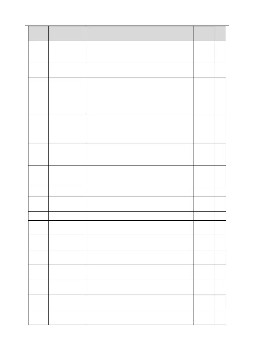
Estimated motor
frequency
The estimated motor rotor frequency under
open-loop vector condition.
Range: 0.00– P00.03
Display current DC bus voltage of the inverter.
Range: 0.0–2000.0V
Digital input
terminal state
Display current digital input terminal state of the
inverter.
0000–03F
Corresponds to HDIB, HDIA, S4, S3, S2 and S1
respectively
Digital output
terminal state
Display current digital output terminal state of the
inverter.
0000–000F
Corresponds to R02, RO1, HDO and Y1 respectively
Digital
adjustment
variable
Display the regulating variable by UP/DOWN
terminals of the inverter.
Range: 0.00Hz–P00.03
Relative to percentage of the rated torque of current
motor, display torque reference.
Range: -300.0%–300.0% (rated motor current)
Display input signal of AI 1
Range: 0.00–10.00V
Display input signal of AI2
Range: 0.00–10.00V
Display input frequency of HDIA
Range: 0.000–50.000kHz
Display input frequency of HDIB
Range: 0.000–50.000kHz
Display PID reference value
Range: -100.0–100.0%
Display PID feedback value
Range: -100.0–100.0%
Display the power factor of current motor.
Range: -1.00–1.00

 Loading...


