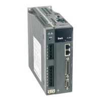
INVT SV-DA200 AC Servo Drive PROFINET Technical Guide V2.63
27
3 Operation modes
3.1Position mode–Bus position
3.1.1 Basic description
The servo driver (slave node) receives a position command from the upper computer (master node). After
electronic gear ratio conversion, the command is used as the target position for internal position control. In
this way, position control is implemented.
When P0.22 is set to a non-zero value:
Position command encoder unit = Position command user unit x Encoder resolution / P0.22
P0.22=Motor PPR
When P0.22 is set to 0:
Position command encoder unit = Position command user unit x P0.25 / P0.26
P0.25=Numerator of gear ratio 1
P0.26=Denominator of gear ratio 1
Note: In this mode, you need to plan parameters such as the speed and acceleration on the PLC.
3.1.2 Operation procedure
1. Set P0.03 [Control mode] (IND = 1006) to 0 [Position mode].
2. Set P4.12 [Bus position command] to the target position (IND = 1824; unit: user unit).
3. Set P0.33 [Position command smooth filter] (IND = 1066). Make the setting take effect immediately.
You can make PZD set parameters (for V2.61 or later).
4. Set P0.34[Position command FIR filter] (IND = 1068) (FIR filter time = PZD control cyclic period).
Disable for the setting to take effect.
5. Set P0.22 (IND = 1044) to adjust the denominator of the gear ratio.
6. Set CW.bit0 (SERVO_DI_INH) to 1, and then set CW.bit1 (SERVO_ON) to enable the servo drive and
start the motor.
7. Query R0.02 (IND = 4004) to obtain the motor actual position feedback (position feedback is the data
of bit 64).
8. Query the SW for corresponding information to obtain the servo drive status feedback (READY, RUN,
POS_CMD_VALID, and POSITION_COIN).
3.1.3 Other objects
1. Set P4.33 (IND = 1866) to adjust the tolerance (unit: user unit).
2. Query R0.04 (IND = 4012) to obtain the motor actual position deviation (unit: user unit).

 Loading...


