SV-DA200 series AC servo drives Faults and solutions
‐123‐
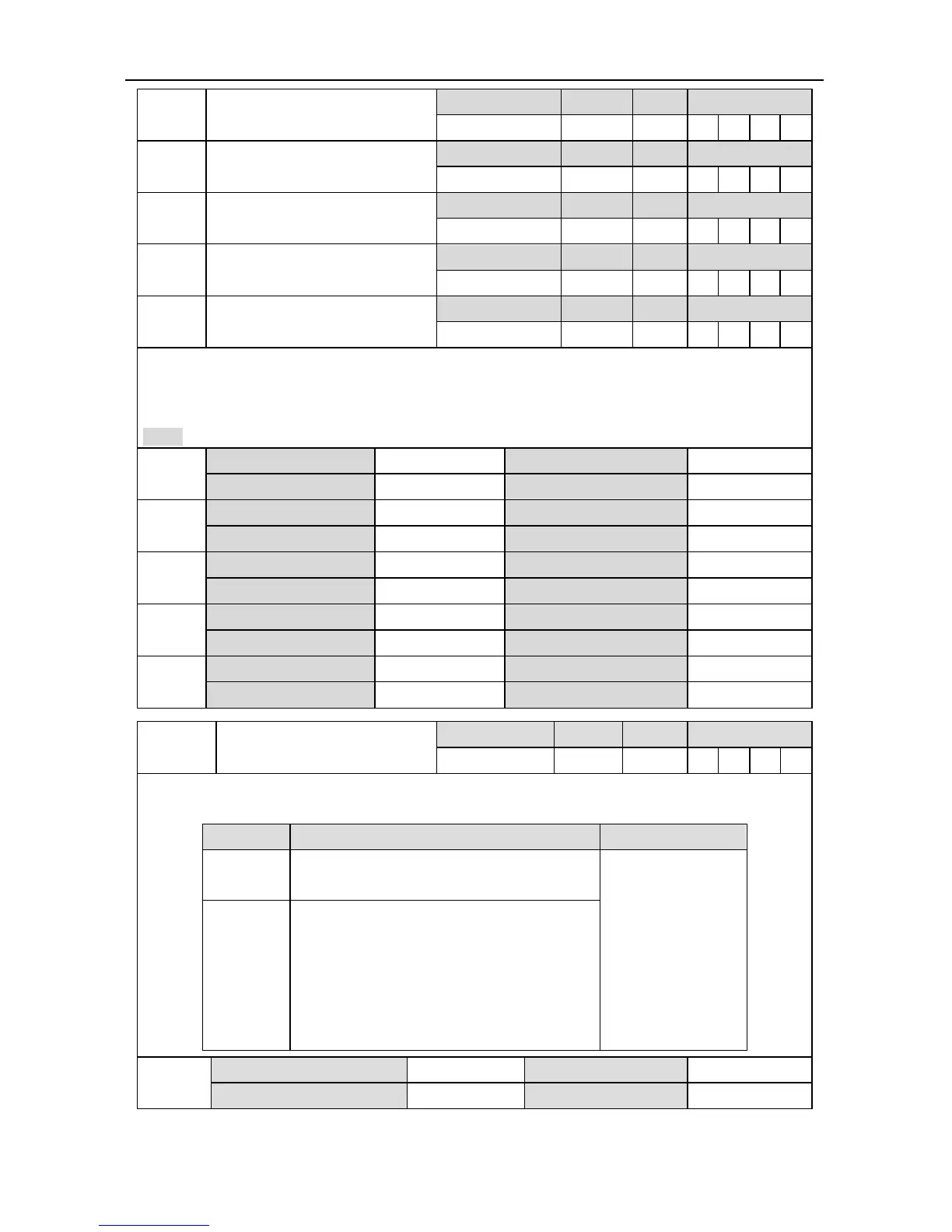
P3.11
1
Output configuration of digital 2
Setting range Default Unit Available mode
0x000~0x11F 0x003 - P S T F
P3.12
1
Output configuration of digital 3
Setting range Default Unit Available mode
0x000~0x11F 0x007 - P S T F
P3.13
1
Output configuration of digital 4
Setting range Default Unit Available mode
0x000~0x11F 0x00D - P S T F
P3.14
1
Output configuration of digital 5
Setting range Default Unit Available mode
0x000~0x11F 0x005 - P S T F
P3.15
1
Output configuration of digital 6
Setting range Default Unit Available mode
0x000~0x11F 0x00E - P S T F
These parameters are used to set the output function of digital value 2~6, and they are hex
numbers.
The setting method is the same as P3.10.
Note: The default value is the function selection corresponds to position mode.
P3.11
1
Data size 16bit Data format HEX
Modbus address 1622, 1623 CANopen address 0x230B, 0x00
P3.12
1
Data size 16bit Data format HEX
Modbus address 1624, 1625 CANopen address 0x230C, 0x00
P3.13
1
Data size 16bit Data format HEX
Modbus address 1626, 1627 CANopen address 0x230D, 0x00
P3.14
1
Data size 16bit Data format HEX
Modbus address 1628, 1629 CANopen address 0x230E, 0x00
P3.15
1
Data size 16bit Data format HEX
Modbus address 1630, 1631 CANopen address 0x230F, 0x00
P3.16
Function configuration of DI
capture encoder
Setting range Default Unit Available mode
0~778 0 - P S T F
DI port capture function configuration, capture the encoder position via the jump edge of DI port
in real time, check encoder value captured via R1.16.
Data bit Setup instruction Remark
bit0~3
bit0~3=0x1~0xA, corresponds to capture
port DI1~DI10
Others are invalid
state
bit8~9
bit8=1, bit9=0, capture only on DI port
falling edge;
bit8=0, bit9=1, capture only on DI port
rising edge;
bit8=1, bit9=1, capture on both DI port
rising edge and falling edge
P3.16
Data size 16bit Data format DEC
Modbus address 1632, 1633 CANopen address 0x2310, 0x00
 Loading...
