SV-DA200 series AC servo drives Control mode applications
‐40‐
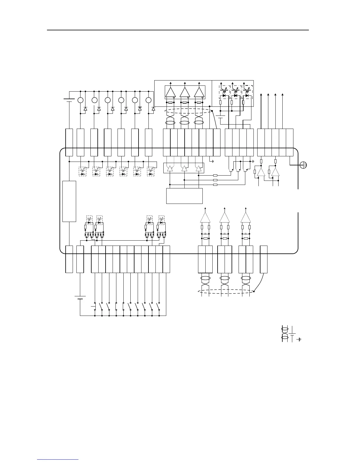
4.2 Standard wiring of the speed mode
Speed control mode
Load capacity of
each output
terminal is
DC30V, 50mA
EMG 39
SON 16
ZRS 37
POT 3
NOT 4
CLA 10
SPD1 34
SPD2 17
S/SIGN 18
PLC 22
Gain switching
Speed command
symbol
Internal speed
command 2
Internal speed
command 1
Alarm clearing
Neg
ative direction
drive disabled
Emergency stop
Servo enabling
Zero speed clamp
Positive direction
drive disabled
COM- 12
COM+ 2
24V 40
Internal DC24V power
Note: Capacity 100mA
12 COM-
15 ALM
14 RDY
29 ZSO
11 COIN
13 LM
9 BRK
FG
21 AO1
5 GND
25 AO2
6 GND
FG
Torque monitoring output
Speed monitoring output
Fault
Servo ready
Speed zero
Speed matching
Torque limiting
Brake release
Speed command input
(-10V~+10V)
AD1 1
GND 5
When non-standard model is selected, AD1
channel is invalid. Please use AD3 channel
and confirm P3.70 is “speed command”.
AD2 20
GND 19
AD3 7
GND 8
Analog torque limit of positive direction
(0V~+10V)
Analog torque limit of negative direction
(-10V~0V)
Note: User-supplied power
DC12~24V
-+
Note: User-supplied power
Vcc≤DC30V
-+
……
Frequency
divider
36 OCA
External
controller
44 OA+
43 OA-
41 OB+
42 OB-
FG
26 OCZ
30 OCB
AM26LS32
or equivalent chip
V
cc
≤DC30V;
OCA/B/Z output
current≤50mA
28 OZ+
27 OZ-
High speed optical
coupler
35 GND
GND
-+
Vcc
5 GND
CN1
Output voltage range:
DC -10V~+10V;
Max output current:
3mA.
DI input
common port
DO output common
ground
Ref
Note: 1. ( ) is shielded twisted pair;
2. ( ) is power which is provided by the user;
3. ( ) is GND, pin numbers are 5/6/8/19/35.
DO output
common ground