SV-DA200 series AC servo drives Faults and solutions
‐84‐
Note: The switching mode is not limited by actual operation.
6 F /
Fully-closed loop mode: Use the linear encoder to detect the
devices of control object and conduct information feedback
position control.
7 CANopen /
CANopen mode (CANopen type servo support)
8 EtherCAT /
EtherCAT mode (EtherCAT type servo support)
9 MotionNet /
MotionNet mode (MotionNet type servo support)
Remark: Set P0.03 and P3.00~P3.09 will switch automatically according to the selected control
mode.
Note:0:OFF (internal optical coupler corresponding to the input is not conducted);
1:ON (internal optical coupler corresponding to the input is conducted).
P0.03
1
Data size 16bit Data format DEC
Modbus address 1006,1007 CANopen address 0x2003, 0x00
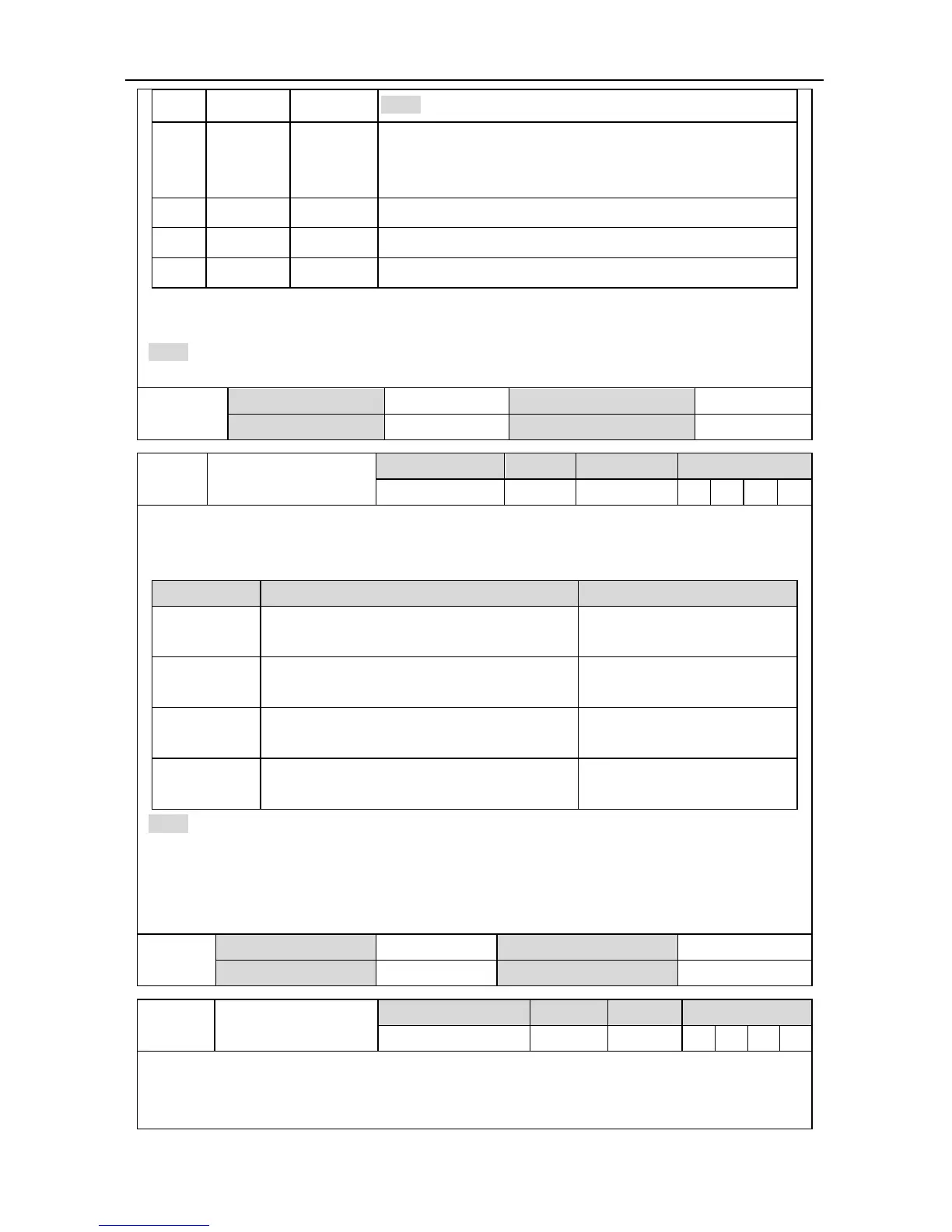
P0.04*
Internal enabling
command
Setting range Default Unit Available mode
0~1 0 - P S T F
This parameter is used to control the operation state of the servo drive.
The relation between internal enable instruction and external terminal enable instruction is
shown below:
Setting value External terminal command state Working state of servo drive
0
0 (internal optical coupler which corresponds
to the input is not conducted)
Stand-by (OFF)
0
1(internal optical coupler which corresponds
to the input is conducted)
Enabling running (ON)
1
0 (internal optical coupler which corresponds
to the input is not conducted)
Enabling running (ON)
1
1 (internal optical coupler which corresponds
to the input is conducted)
Enabling running (ON)
Note:
1. When P0.04 is 1 and the external terminal command converts from 1 to 0, the servo drive will
be disabled, namely P0.04 will change to 0 automatically.
2. When this parameter is operated via the LED panel, it can only be switched between 0 and 1
via SET key and UP/DOWN key is invalid under the setup interface of this parameter.
P0.04*
Data size 16bit Data format DEC
Modbus address 1008,1009 CANopen address 0x2004, 0x00
P0.05 JOG speed
Setting range Default Unit Available mode
0~1000 200 r/min P S T F
This parameter can be used to set the jog speed. For jogging, please refer to chapter 5.2.5.2
During jogging, the ACC/DEC time parameters (P0.54, P0.56, P0.55, and P0.57) are active.
The motor will accelerate, decelerate, start and stop according to the settings.
 Loading...
