IP Gear SmartCell 111L User Guide
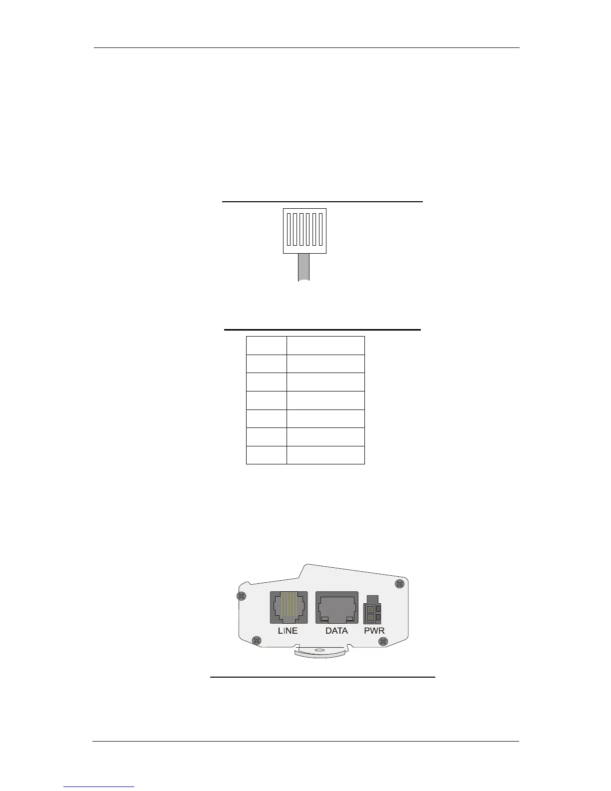
3.1.5 RJ-11 Connector Pin Layout
Figure 3-1 illustrates the pin layout of the RJ-11 line connector. Table 3-1 details
the pin-to-wire layout of the RJ-11 connector. One end of the cable is connected
to the (FXS) Line interface of the Smartcell 111L and the other end is connected
to the (FXO) trunk interface of the PABX.
Figure 3-1: RJ-11 Connector pin layout
1 2 3 4 5 6
Table 3-1: RJ-11 Connector Pin Layout
PIN # FUNCTION
1 Reserved
2 Tip
3 Tip
4 Ring
5 Ring
6 Reserved
Warning: Do not use the reserved pins.
Note: The line can use either pins 3 and 4 or pins 2 and 5.
3.1.6 Connection Panel
Figure 3-2: SmartCell 111L Connector Panel
Page 8