iPECS-MG Quick Start Guide
I
Table of Contents
1 SYSTEM OVERVIEW ........................................................................... 1
1.1 iPECS-MG System Connection Diagram .................................................. 1
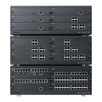
1.2 System Components
.................................................................................. 2
2 KSU INSTALLATION ........................................................................... 3
2.1 BKSU/EKSU Unpacking ............................................................................. 3
2.2 Power Supply Unit Installation
.................................................................. 5
2.3 Frame Ground Connection
........................................................................ 6
2.4 External Backup Battery Installation
........................................................ 6
2.5 KSU Mounting
............................................................................................. 7
2.5.1 Wall Mounting / Rack Mounting .................................................................................. 7
2.6 Expansion KSU Installation ....................................................................... 9
3 BOARD INSTALLATION ................................................................... 10
3.1 Installation of the Boards ......................................................................... 10
3.2 Main Processing Board 100/300 (MPB100/MPB300)
............................. 11
3.2.1 Modular Jack (MJ1, MJ3) ......................................................................................... 11
3.2.1.1 MJ1 Pin Assignment ................................................................................................. 11
3.2.1.2
MJ3 (Alarm Detection and Relay Contact) Pin Assignment ...................................... 12
3.2.2 DSIU (Digital and Single line Interface Unit) ............................................................. 12
3.2.2.1 Pin Assignment ......................................................................................................... 12
3.2.3 MODU (MODEM Interface Unit) ............................................................................... 12
3.3 CO Line Boards ......................................................................................... 13
3.3.1 LCOB4/LCOB8/LCOB12 (Loop Start CO Line Interface Board) .............................. 13
3.3.1.1 Pin Assignment ......................................................................................................... 13
3.3.1.2
CMU4 (Call Metering detection Unit) ......................................................................... 13
3.3.2 BRIB2/BRIB4 (Switchable S/T Interface Board) ....................................................... 14
3.3.2.1 Pin Assignment ......................................................................................................... 15
3.3.2.2
Connectors and Switch Functions ............................................................................. 15
3.3.3 PRIB (Primary Rate Interface Board) ....................................................................... 16
3.3.3.1 Pin Assignment ......................................................................................................... 17
3.4 Extension Boards ..................................................................................... 18
3.4.1 SLIB12/24 (Single Line Interface Board) .................................................................. 18
3.4.1.1 Pin Assignment ......................................................................................................... 19
3.4.2 SLIB12C/24C (with RJ21 connector) ....................................................................... 19
3.4.3 DTIB12/24 (Digital Terminal Interface Board) .......................................................... 20
3.4.3.1 Pin Assignment ......................................................................................................... 20