5
Installing the Valves
CAUTION: Maximum screw torque not to exceed 5 inlbs.
1. Route the valve wires or wire cable from the valves, into
the controller cabinet.
Note:
18AWG (1.0mm2) multiwire sprinkler valve
connection cable can be used. This cable is insulated for
direct burial and is colorcoded to simplify installation.
It can be routed directly into the controller through the
access hole provided for valve wire conduit (if conduit is
not used).
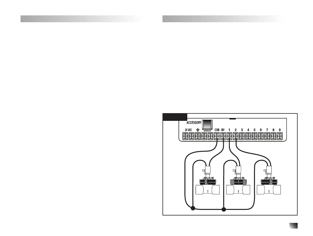
2. Attach the white colorcoded wire from the cable to one
wire from each valve solenoid. (Either solenoid wire can
be used for this connection.) This is called the “Valve
Common” wire. See Figure 2.
3. Attach a separate cable wire to the remaining wire from
each valve solenoid. Note the wire color code used
for each valve and the watering station it controls. You
will need to have this information when connecting the
valve wires to the controller.
4. Secure all wire splices using wire nut connectors. To
prevent corrosion and possible short circuits, always
use an insulated wire nut, grease cap or similar
waterproong method.
5. At the controller end of the valve connection cable,
strip back 1⁄4" (6mm) of insulation from all cable wires
6. Secure the Valve Common wire to the terminal labeled
COM. Connect the individual valve wires to the
appropriate station terminals. Connect the master valve
wire (if applicable) to the terminal labeled MV.
Note: Connecting a master valve or pump start relay
is optional and may not be required for your sprinkler
system.
Installing a Pump Start Relay
CAUTION: To prevent controller damage, ensure the pump
start relay current draw does not exceed 0.4A. Do not
connect the pump motor starter directly to the controller.
1. Connect a wire pair to the 24VAC pump start relay.
Route the wires into the controller housing with the
valve wires.
2. Connect one wire to the terminal labeled COM .
Connect the remaining wire to the terminal labeled MV.
See Figure 2.
CAUTION:
To prevent pump damage due to “Dead
heading,” connect a jumper wire from any unused station
terminal to a station terminal with a valve connected.
ACCESSORY
24 VAC COM
SENSOR
MV
123456789
Master
Valve
Station 1 Station 2
Figure 2