6
Installing a Rain Sensor (optional)
A rain sensor can be connected directly to the KD2 to
automatically interrupt watering when it begins to rain.
When the rain sensor absorbs rain water, it automatically
signals the KD2 to suspend all watering operations. The
display will alternately show SEN (sensor) and the time of
day until the rain sensor drys out and resets the controller
for automatic operation.
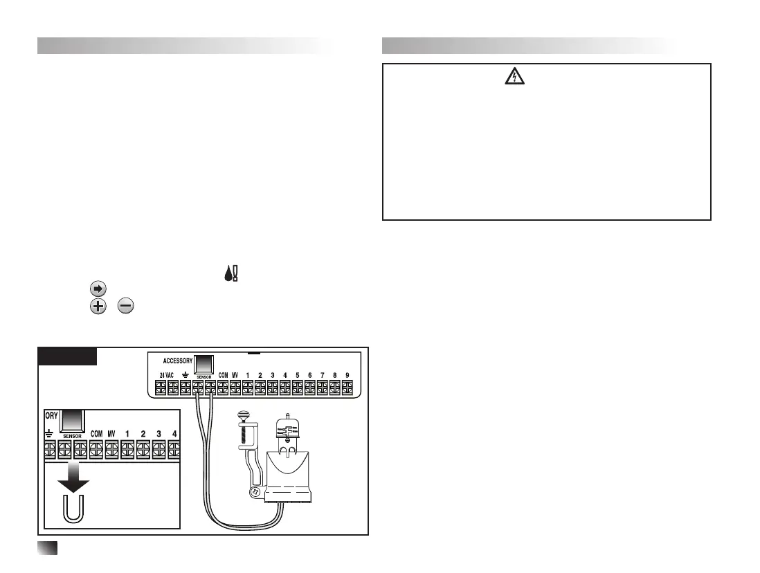
1. Route the wire cable from the rain switch sensor into
the controller along with the valve wires.
2. Remove the jumper wire from the sensor terminals.
3. Referring to the instructions provided with the rain
sensor, connect two wires from the rain sensor
designated for “Normally Closed” applications to the
sensor terminals. See Figure 3.
4. Once powered, turn the dial to Special Functions.
Press
and scroll to RS Y (Rain Sensor Yes).
Press
/ to set sensor to RS Y (active) or RS N
(Bypass).
Note: The default setting is RS Y (active).
Connecting the Power Source
WARNING
AC power wiring must be installed and connected by
qualied personnel only. All electrical components and
installation procedures must comply with all applicable
local and national electrical codes. Some codes may
require a means of disconnection from the AC power
source installed in the xed wiring and having a contact
separation of at least 0.120” (3mm) in the line and
neutral poles. Make sure the power source is OFF prior
to connecting the controller.
1. Verify that the power is turned o at the source.
2. Remove the power connection access cover.
3. Route the power and equipment ground wires from the
power source through conduit into the controller power
connection compartment. For wire restraint, route the
cable inside the compartment as shown in Figure 4 A.
Note: The international model terminal block accepts
wire size up to 4 mm
2
.
4. For nonUS models, use the terminal block which
accepts wire size up to 4 mm
2
(Brown for line, Blue for
neutral and Green for earth ground). For US models,
use the wire nuts provided, secure Line to the Black
wire, Neutral to the White wire and Equipment Ground
to the Green wire. See Figure 4 B and C.
5. Install and secure the power wire access cover.
ACCESSORY
24 VAC COM
SENSOR
MV
123456789
Figure 3
COM
SENSOR
MV
Wire Jumper