Inspection and Installation
The above picture is only used to demonstrate the installation process of
the communication box. The actual appearance of the rear panel of the
power supply should be subject to the actual product.
3. Install the purchased communication card.
a. Use a screwdriver to unscrew the screws above the communication card.
b. Push the communication card into the instrument slot.
c. Use the screwdriver and screws to lock the instrument and the communi-
cation card.
4. After the communication card is installed successfully, power on the
instrument.
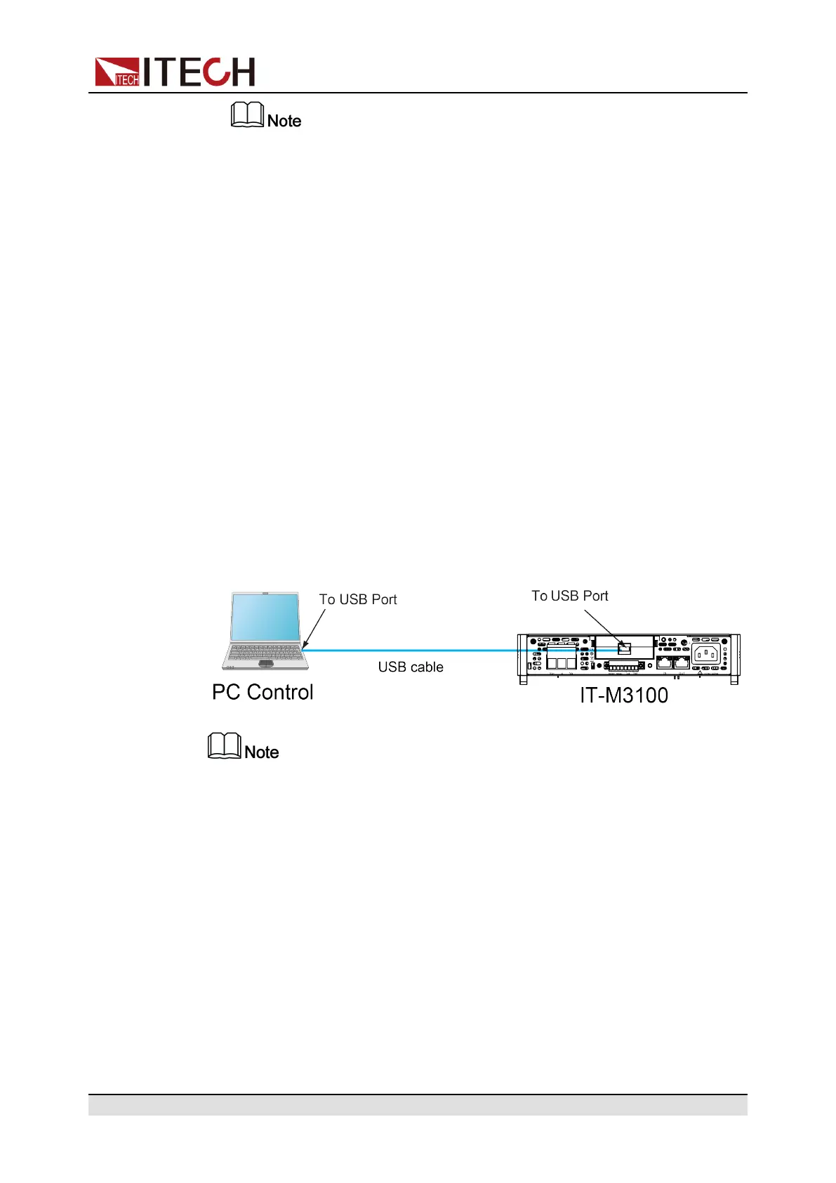
2.7.1 USB Interface
When the optional interface card is a stand-alone USB interface (IT-E1209) or
USB+LAN interface (IT-E1206), the following can help users quickly understand
the steps required to connect the USB interface. The figure below shows a typi-
cal USB interface system.
• Take the IT-E1209 communication card box as an example. If you install IT-
E1206, please refer to the actual interface position.
• The rear panel shown in the figure is only an example. The actual appearance of
the rear panel is subject to the specific instrument.
This series of power supply USB interfaces include the following two types,
which do not need to be set in the menu, and can be operated remotely after in-
stalling the driver and connecting the USB communication cable.
• TMC: USB_TMC type interface, you need to install the NI-VISA driver
adapted to the computer operating system version. Please download the
driver from the NI official website. After the driver is installed successfully, it
will be recognized as the USB device address in the computer device man-
ager. As below.
Copyright © Itech Electronic Co., Ltd.
25